 |
|
 05-10-2019, 11:58
|
#16
|
|
Registered User

Join Date: Aug 2013
Location: Florida
Boat: 2000 Searay 380 Sundancer
Posts: 1,087
|
Re: Shaft alignment with flexible coupling
Quote:
Originally Posted by wingless

The purpose of the Vetus Type 6 flexible coupler is to tolerate misalignment between the engine and the output shaft.
It is best to adjust for best alignment between the parts.
The conical clamping hub permits coupler movement to the shaft of the parts shown in the first image.
A pair of small 123 blocks could be used to position the coupler half face in the first image to be perpendicular to the shaft. Once block placed on the shaft, to get the back side above the conical clamping hub, then the second block to get the back side of the coupler perpendicular to the shaft.
Then feeler gauges between the coupler faces and vernier calipers around the perimeter would permit setting the motor mounts for correct vertical, lateral and angular alignment.
https://www.vetus.com/media/magentom...09103940_0.pdf |
A better option than making the back surface perpendicular to the shaft is to instead make the face surface perpendicular to the shaft.
A vee block on the shaft w/ a square touching the face surface and the vee block at two places 90 degrees apart would get the face surface perpendicular to the shaft.

__________________
2000 SeaRay 380 Sundancer Mercruiser
454 MAG MPI Horizon 380hp / Westerbeke 7.0KW BCGB
many cool mods
|

|

|
|
05-10-2019, 12:05
|
#17
|
|
Registered User
Join Date: Aug 2013
Location: Florida
Boat: 2000 Searay 380 Sundancer
Posts: 1,087
|
Re: Shaft alignment with flexible coupling
Quote:
Originally Posted by Q Xopa
Agreed. Nice diagrams.
They show why the usual feeler gauge method only measure 'angular misalignment'.
|
Correct. Thanks.
When I aligned my vee drive engines / transmissions to be “dead on balls accurate” I needed to first create a procedure that accounts for the weird geometry. It worked great!
Now I have my “Certificate of Validation “.
__________________
2000 SeaRay 380 Sundancer Mercruiser
454 MAG MPI Horizon 380hp / Westerbeke 7.0KW BCGB
many cool mods
|
|
|
|
|
05-10-2019, 13:19
|
#18
|
|
Registered User
Join Date: Feb 2017
Location: Panama, Central America
Boat: CT 49, 1989
Posts: 969
|
Re: Shaft alignment with flexible coupling
V drive is usually an access challange. But it is actually still the same, ie aligning the Transmission output flange to the propeller shaft.
My preferred procedure is using a pair of dial gauges.
One attached to the engine output and reading on the prop shaft.
The other attached to the prop shaft and reading on the engine output.
The good thing about this procedure is only need a 12, 3 and 9 o'clock reading.
And the readings are 'live' so you can see as you are doing adjustments exactly how much is required.
|
|
|
|
|
05-10-2019, 13:28
|
#19
|
|
Registered User
Join Date: Aug 2013
Location: Florida
Boat: 2000 Searay 380 Sundancer
Posts: 1,087
|
Re: Shaft alignment with flexible coupling
Quote:
Originally Posted by wingless
When I aligned my vee drive engines / transmissions to be dead on balls accurate I needed to first create a procedure that accounts for the weird geometry. It worked great!
|
Quote:
Originally Posted by Q Xopa
V drive is usually an access challange. But it is actually still the same, ie aligning the Transmission output flange to the propeller shaft. |
Yes the objectives are the same.
Attaining those objectives in a methodical method, instead of the typical hit and miss approach was the thought challenge.
The easiest geometry is the straight drive.
Both the down angle and the vee drive have complexity that must be understood to attain great results quickly.
__________________
2000 SeaRay 380 Sundancer Mercruiser
454 MAG MPI Horizon 380hp / Westerbeke 7.0KW BCGB
many cool mods
|
|
|
|
|
05-10-2019, 14:02
|
#20
|
|
Registered User
Join Date: Jun 2019
Location: Bay of Islands New Zealand
Boat: Morgan 44 CC
Posts: 1,136
|
Re: Shaft alignment with flexible coupling
 Learn something new every day, Ive not seen one of these before.
Despite the preceding statement, if that coupling was on my boat, I believe I would want to be sure that the four rubber bushings rotated freely on their spindles. Reckon if they got seized up, the flexibility would be significantly reduced. I base this assumption purely on my knowledge of how a needle-rollered universal joint works.
YMMV
|
|
|
|
|
05-10-2019, 14:30
|
#21
|
|
Registered User
Join Date: Feb 2017
Location: Panama, Central America
Boat: CT 49, 1989
Posts: 969
|
Re: Shaft alignment with flexible coupling
Quote:
Originally Posted by CassidyNZ
[emoji2] Learn something new every day, Ive not seen one of these before.
Despite the preceding statement, if that coupling was on my boat, I believe I would want to be sure that the four rubber bushings rotated freely on their spindles. Reckon if they got seized up, the flexibility would be significantly reduced. I base this assumption purely on my knowledge of how a needle-rollered universal joint works.
YMMV |
Mine are a lot smaller than the pic Ive attached.
Forgot to mention, also dont need to disconnect the coupling. 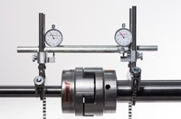
|
|
|
|
|
05-10-2019, 21:05
|
#22
|
|
Registered User
Join Date: Jun 2019
Location: Bay of Islands New Zealand
Boat: Morgan 44 CC
Posts: 1,136
|
Re: Shaft alignment with flexible coupling
Quote:
Originally Posted by Q Xopa
Mine are a lot smaller than the pic Ive attached.
Forgot to mention, also dont need to disconnect the coupling. Attachment 200983 |
Yours is not a Vetus Type 6 then as is the original post. His looks like the two images below (I believe).
If the coupling you posted is what is on your boat, it looks like a normal machine coupler, I use one to hook planers, jointers, etc. to an electric motor stand in my workshop. If Im not mistaken the one you show has no actual connection between shaft and drive (see third image).
If that is so, I reckon thats quite dodgy What stops the shaft retracting when reversing?
|
|
|
|
|
05-10-2019, 22:57
|
#23
|
|
Registered User
Join Date: Dec 2017
Location: Esperance WA
Boat: Passport40
Posts: 13
|
Re: Shaft alignment with flexible coupling
[QUOTE]
Quote:
Originally Posted by CassidyNZ
Yours is not a Vetus Type 6 then as is the original post. His looks like the two images below (I believe). |
Yep Cassidy that's exactly what i got....
there has been some good advise thus far, so thanks to all who replied 
As a surveyor by trade this alignment i thought would be a straight forward process  the complication being the flexible coupling and the tiny tranny flange (the coupling is close to double the diameter of the tranny flange). In my mind im still having trouble visualizing the process, i guess once i,ve had a go at it, it may all become clearer ??
Wingless the spacer blocks method i believe is my best bet, but that assumes if i'm correct that the inside face of the coupler is indeed square to the shaft, which i guess it should be as with a normal flange. I'll be back at the boat tomorrow so will have another look and do a bit more thinking.
Cheers, Scott
|
|
|
|
|
05-10-2019, 23:18
|
#24
|
|
Registered User
Join Date: Feb 2017
Location: Panama, Central America
Boat: CT 49, 1989
Posts: 969
|
Re: Shaft alignment with flexible coupling
Quote:
Originally Posted by CassidyNZ
Yours is not a Vetus Type 6 then as is the original post. His looks like the two images below (I believe).
If the coupling you posted is what is on your boat, it looks like a normal machine coupler, I use one to hook planers, jointers, etc. to an electric motor stand in my workshop. If Im not mistaken the one you show has no actual connection between shaft and drive (see third image).
If that is so, I reckon thats quite dodgy [emoji2] What stops the shaft retracting when reversing? |
I was referring to the what concept of aligning shafts with dial gauges looks like.
My propeller shaft coupling is a Sigma drive. But Vetus/ Sigma/ V drive or even electric machinery shaft alignment is the same principle.
|
|
|
|
|
06-10-2019, 06:32
|
#25
|
|
Registered User
Join Date: Aug 2013
Location: Florida
Boat: 2000 Searay 380 Sundancer
Posts: 1,087
|
Re: Shaft alignment with flexible coupling
Quote:
Originally Posted by Wayfarer111
Wingless the spacer blocks method i believe is my best bet, but that assumes if i'm correct that the inside face of the coupler is indeed square to the shaft, which i guess it should be as with a normal flange.
|
No the coupler does not need to be square to the shaft.
The coupler has a universal joint to permit any angle, within the range of that joint.
Prior to alignment, set the coupler face to be perpendicular to the shaft.
__________________
2000 SeaRay 380 Sundancer Mercruiser
454 MAG MPI Horizon 380hp / Westerbeke 7.0KW BCGB
many cool mods
|
|
|
|
|
06-10-2019, 13:06
|
#26
|
|
Registered User
Join Date: Jun 2019
Location: Bay of Islands New Zealand
Boat: Morgan 44 CC
Posts: 1,136
|
Re: Shaft alignment with flexible coupling
Looking at the exploded view of the Vetus coupler, it would seem that it would always be perpendicular to the shaft. The diagram shows a cross through the key (top left) which implies that the tapered collar serves the function of locking the coupler to the shaft (at least it does to me ).
@Wayfairer - with the new engine mounts that you have installed it should be possible to eliminate the need for a flex coupler if you so desired. Adjusting the attitude of the engine/transmission in the traditional way would bring the face of a normal shaft flange exactly parallel with the transmission side of the coupler.
But then again, that means a whole lot of new parts (read $$$) and thats perhaps the silly way to solve it. I personally have a notable shortage of $$$.
|
|
|
|
|
09-10-2019, 15:44
|
#27
|
|
Registered User
Join Date: Dec 2017
Location: Esperance WA
Boat: Passport40
Posts: 13
|
Re: Shaft alignment with flexible coupling
Yeah Classidy I'm getting a flange made up and will remove the flexible one....dammit more $$$. I spoke to Shipwright in Albany and he reckoned it would be the best way to go
|
|
|
|
|
|
| Thread Tools |
Search this Thread |
|
|
|
| Display Modes |
Rate This Thread |
 Linear Mode Linear Mode
|
|
 Posting Rules
|
You may not post new threads
You may not post replies
You may not post attachments
You may not edit your posts
HTML code is Off
|
|
|
|
Advertise Here

 Recent Discussions Recent Discussions |
|
|
|
|
|
|
|
|
|
|
|
|
|
|
|
|
|
|
|
|
|
|
|
|
|
Vendor Spotlight |
|
|
|
|
|
|
|
|
|


