 |
|
 15-05-2017, 13:52
|
#16
|
|
Registered User

Join Date: Jul 2015
Location: San Rafael, Ca.
Boat: Gaff rigged Ketch[Spray]37' on deck
Posts: 602
|
Re: Separating Inverter and Shore Circuits
The big thing you hafto worry about is having the shore power going in the back door of the inverter [no switch], it will blow out the FET's[ large diodes] and ruin the inverter, i don't like the automatic configuration and allways put in a rotary switch [blue seas].
|

|

|
|
15-05-2017, 14:44
|
#17
|
|
cruiser
Join Date: Jan 2012
Location: Lake Ontario
Boat: Ontario 38 / Douglas 32 Mk II
Posts: 3,250
|
Re: Separating Inverter and Shore Circuits
Quote:
Originally Posted by mikereed100

A friend has separated the inverter and shore/generator circuits on his boat such that in all the outlets the upper socket is wired to the shore/generator circuit and the lower socket is wired to the inverter. I can't think of a good reason to do this unless, for some reason, he wants to run the inverter and shore power at the same time. To me it makes more sense to just switch from one to the other using a source selector switch, but what do I know? Anybody see any advantage to separating the circuits? |
Not ABYC compliant. You can only have one AC source connected to the AC single AC distribution panel at a time. Additionally, when shore power is the source the grounded current carrying conductor must be grounded at the
Source. For shore power, this is at the marina AC distribution panel. For
On board sources, this is the generator or
Inverter. It would be possible to switch the ground so the single
Ground connection on each receptacle and hard wired device was switched, but by virtue of the beast, there is no way to run two different grounds at the same time, so one can't be compliant operating shore power and inverter, or
Shore power and generator, or generator and inverter at the same
Time.
Sorry about format, keyed
In on my pos iphone
|
|
|
|
|
15-05-2017, 16:54
|
#18
|
|
Registered User
Join Date: Jul 2012
Boat: Tayana 58 DS
Posts: 763
|
Re: Separating Inverter and Shore Circuits
Quote:
Originally Posted by ramblinrod
Not ABYC compliant. You can only have one AC source connected to the AC single AC distribution panel at a time. Additionally, when shore power is the source the grounded current carrying conductor must be grounded at the
Source. For shore power, this is at the marina AC distribution panel. For
On board sources, this is the generator or
Inverter. It would be possible to switch the ground so the single
Ground connection on each receptacle and hard wired device was switched, but by virtue of the beast, there is no way to run two different grounds at the same time, so one can't be compliant operating shore power and inverter, or
Shore power and generator, or generator and inverter at the same
Time.
Sorry about format, keyed
In on my pos iphone |
In our system, there is only one ground on the whole boat. (I don't think I said otherwise. Ground is not the same as neutral). Every AC outlet and load is connected to the same ground.
There are hots & neutrals from shorepower, genset, and inverter. The showerpower/genset are switched via 2-pole switch -- one or the other of them is connected at any one time. When the charger/inverter (Victron 5000/24/120) has stable input AC input, it drives the inverter output directly from that -- connecting both hot and neutral from inverter AC to genset/shorepower AC. When it derives inverter output instead from inverted DC, the inverter drives hot/neutral. The inverter can be set such that when the input AC load exceeds a set value (which includes all high-load AC, the battery charger itself, and the inverter power), it supplements the AC-out with power from the batteries. There's an aspect of this that doesn't work well, but that is another matter).
This way you can have inverter AC power for lower-power loads, genset/shorepower for higher load.
|
|
|
|
|
15-05-2017, 18:20
|
#19
|
|
Registered User
Join Date: Jul 2016
Location: Traverse City, Michigan
Boat: Hinterhoeller Niagara 35
Posts: 289
|
Re: Separating Inverter and Shore Circuits
The simplest and SAFEST system uses a double pole relay that has its coil energized when shore power is connected. The relay automatically disconnects inverter power and connects shore power when shore power is connected. With no switch to forget potential damage to the inverter due to an out of phase condition is automatically avoided.
Many full featured inverters have this automatic disconnect feature built in.
Monkeying around with rigged up line voltage systems is a bad idea. For those who want to work on their own boats I suggest:
Boatowner's Illustrated Electrical Handbook by Charlie Wing
|
|
|
|
|
16-05-2017, 06:48
|
#20
|
|
cruiser
Join Date: Jan 2012
Location: Lake Ontario
Boat: Ontario 38 / Douglas 32 Mk II
Posts: 3,250
|
Re: Separating Inverter and Shore Circuits
Quote:
Originally Posted by accomplice
In our system, there is only one ground on the whole boat. (I don't think I said otherwise. Ground is not the same as neutral). Every AC outlet and load is connected to the same ground.
There are hots & neutrals from shorepower, genset, and inverter. The showerpower/genset are switched via 2-pole switch -- one or the other of them is connected at any one time. When the charger/inverter (Victron 5000/24/120) has stable input AC input, it drives the inverter output directly from that -- connecting both hot and neutral from inverter AC to genset/shorepower AC. When it derives inverter output instead from inverted DC, the inverter drives hot/neutral. The inverter can be set such that when the input AC load exceeds a set value (which includes all high-load AC, the battery charger itself, and the inverter power), it supplements the AC-out with power from the batteries. There's an aspect of this that doesn't work well, but that is another matter).
This way you can have inverter AC power for lower-power loads, genset/shorepower for higher load. |
I am not sure if you are getting my point.
Per ABYC definitions and colour codes, the black wire is the "ungrounded" current carrying conductor, the white wire is the "grounded" current carrying conductor and the green wire is the "grounding", non current carrying conductor.
If we all use these definitions we should be able to keep it straight.
The "grounding" green conductor in the AC power system, must be connected to the source.
For shore power, the "grounding" connection is through a prong in the shore power cord, that connects back to the marina AC distribution panel, and somewhere, a rod driven into the earth.
For a generator or inverter produced AC on-board, the shore power "grounding" connection must be opened, and the "grounding" conductors connected to the "grounding" connection on the inverter or generator. Some inverters do not have a "grounding" connection (isolated output) and therefore cannot be connected to the vessel AC system and be compliant.
Per ABYC, 2 sources of AC power (even two shore power cords) cannot be connected to the same AC distribution system at the same time.
Because AC receptacles and GFCIs have only one "grounding" connection, even if a duplex receptacle has each socket isolated, and one connected to the shore power and the other to an inverter, thereby being two separate AC distribution systems, because they share the "grounding" connection, which by the standard must be connected to "the" (one and only) source, there is no way to make this ABYC compliant.
Personally, I would never do this. Even if someone proceeds like this, and makes the system non ABYC compliant, there should be a label at every receptacle socket, indicating the source. IMHO, painting a specific colour is not acceptable. This is not a standard, and means nothing to anyone else.
IMHO the best solution is a marine grade inverter, that :
1. Automatically feeds shore power / generator AC and corresponding "grounding" connection to the AC distribution panel when available, and feeds inverter produced AC and "grounding" connection when not.
2. Automatically disables the charger when the inverter is operating.
3. Automatically starts the generator (if applicable) and switches the "grounding" connection, at the minimum battery cycle voltage desired (e.g. 50% DOD)
4. Automatically disables the inverter, if the battery voltage drops below 70% DOD).
This is how my personal vessel is set up (though no generator) and I set up customer electrical systems with inverters.
I have removed and replaced an inverter on a customer vessel (not installed by me) that a surveyor correctly declared "non-compliant to ABYC standards" because it did not have a source "grounding" connection and transfer method when the inverter was in use.
I have also seen vessels where the owner made DIY modifications to have some isolated inverter powered AC receptacles, and other shore power / generator dedicated AC receptacles.
In my opinion, this needlessly cuts up the boat, and makes it less safe.
I disagree that this is a KISS approach. There is little more simple than an auto "grounding" transfer connection relay. It basically removes all operator error possibilities, (like an auto battery combiner compared to an A, B, A/B, Off manual battery switch).
If one does not understand electrical systems well enough to install one, they really shouldn't be mucking about with the vessel electrical system.
|
|
|
|
|
16-05-2017, 07:09
|
#21
|
|
Registered User
Join Date: Feb 2012
Location: East Coast, USA
Boat: Cooper 416
Posts: 91
|
Re: Separating Inverter and Shore Circuits
Quote:
Originally Posted by ramblinrod
For shore power, the "grounding" connection is through a prong in the shore power cord, that connects back to the marina AC distribution panel, and somewhere, a rod driven into the earth.
For a generator or inverter produced AC on-board, the shore power "grounding" connection must be opened, and the "grounding" conductors connected to the "grounding" connection on the inverter or generator. Some inverters do not have a "grounding" connection (isolated output) and therefore cannot be connected to the vessel AC system and be compliant.
|
...and this was my point going back to the OP system. By not following ramblinrod's point (opening the shore power "grounding" connection when using the inverter) you wind up with the shore power grounded connection connected to the generator/inverter grounded connection via their grounding connections. At the very least this presents a surprise shock hazard at the inverter output when the inverter is unpowered and shore power is in use.
So to switch the grounding connection as well I decided a 3 pole relay was needed as a transfer switch.
__________________
Doug
|
|
|
|
|
16-05-2017, 21:09
|
#22
|
|
Registered User
Join Date: May 2010
Location: NW Washington State
Boat: Yankee Dolphin 24'
Posts: 238
|
Re: Separating Inverter and Shore Circuits
Especially if you have an auto-transfer inverter, separating out the outlets for things like heaters and A/C units onto shore-power-only outlets, and everything else on switchable Inverter outlets, can save your batteries (as a friend of mine found out the hard way).
|
|
|
|
|
17-05-2017, 07:59
|
#23
|
|
cruiser
Join Date: Jan 2012
Location: Lake Ontario
Boat: Ontario 38 / Douglas 32 Mk II
Posts: 3,250
|
Re: Separating Inverter and Shore Circuits
Quote:
Originally Posted by tenchiki
Especially if you have an auto-transfer inverter, separating out the outlets for things like heaters and A/C units onto shore-power-only outlets, and everything else on switchable Inverter outlets, can save your batteries (as a friend of mine found out the hard way).
|
Separate outlets for shore power vs inverter AC is a lot of work for little benefit and possible detriment.
All one has to do, to prevent excess battery drain, in the event someone kicks the shore power cord, is:
1. Disconnect any unnecessary AC loads while away from the vessel.
2. Set the inverter low-voltage cut-off to the minimum value desired.
Often these are factory set to a very low value, perhaps 10.5 Vdc to avoid nuisance cut-off when applying a temporary, very high load, on a small bank, and experiencing voltage sag.
Typically, we don't want to take a bank of FLA batteries below 12.20 Vdc (no load, no charge present).
However, for an extreme circumstance, like someone accidentally disconnecting the shore power cord, we may want to allow that to go a little lower, allowing a small amount of life expectancy taken off the batteries, in order to preserve the food in the fridge if possible, let's say, 11.80 Vdc.
If the batteries are good, they will tolerate this deep of discharge, once, with negligible hurt, if immediately recharged fully.
If the boat is abandoned, and the batteries are left at 11.80 Vdc for weeks, their life expectancy may be reduced a bit.
If they are "destroyed" by this, they were most likely due for replacement anyway.
If it happens frequently, perhaps it's a better idea to come up with a better way to secure the shore power cord, than to cut the boat up installing unsightly isolated receptacles all over.
PS, a shore power cord that can come loose easily is a potential fire hazard. Solve the root problem, don't mask it.
|
|
|
|
|
17-05-2017, 11:09
|
#24
|
|
Registered User
Join Date: Mar 2013
Location: East of the river CT
Boat: Oday Mariner 19 , Four Winns Marquis 16 OB, Kingfisher III
Posts: 657
|
Re: Separating Inverter and Shore Circuits
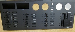
Most of the boat builders and refit guys we build panels for tend to break out a section of loads for the inverter. Typically it's all the outlets, and maybe a microwave or something else if it's a really big inverter. Here is an example the first column is on a charger inverter with auto switch over so when inverting the other loads (high draw) can't come on. Works well from a user stand point.
__________________
mysite: Colinism.com
|
|
|
|
|
17-05-2017, 11:35
|
#25
|
|
Registered User
Join Date: Mar 2013
Location: East of the river CT
Boat: Oday Mariner 19 , Four Winns Marquis 16 OB, Kingfisher III
Posts: 657
|
Re: Separating Inverter and Shore Circuits
Quote:
Originally Posted by dsteinfeld
...and this was my point going back to the OP system. By not following ramblinrod's point (opening the shore power "grounding" connection when using the inverter) you wind up with the shore power grounded connection connected to the generator/inverter grounded connection via their grounding connections. At the very least this presents a surprise shock hazard at the inverter output when the inverter is unpowered and shore power is in use.
So to switch the grounding connection as well I decided a 3 pole relay was needed as a transfer switch. |
Technically ABYC says no switch or overcurrent protection should be installed on the Grounding conductor (green one here in the US).
__________________
mysite: Colinism.com
|
|
|
|
|
17-05-2017, 14:23
|
#26
|
|
Registered User
Join Date: Jun 2007
Location: SW Florida
Boat: FP Belize, 43' - Dot Dun
Posts: 3,823
|
Re: Separating Inverter and Shore Circuits
Quote:
Originally Posted by tenchiki
Especially if you have an auto-transfer inverter, separating out the outlets for things like heaters and A/C units onto shore-power-only outlets, and everything else on switchable Inverter outlets, can save your batteries (as a friend of mine found out the hard way).
|
Quote:
Originally Posted by ramblinrod
Separate outlets for shore power vs inverter AC is a lot of work for little benefit and possible detriment.
|
I have (2) AC distribution panels, the main one fed from shorepower/generator. I have a breaker in the main panel that feeds the inverter/charger which then feeds a second panel. The inverter has a transfer switch built in. The only thing in the second panel are 3 circuits of outlets. AC, watermaker, washer/dryer, water heater are all fed from the main panel. No chance of draining batteries with too heavy a load.
FWIW, the shorepower/generator switch breaks/switches the ground between sources also (like it's suppose to).
|
|
|
|
|
17-05-2017, 18:16
|
#27
|
|
Registered User
Join Date: Feb 2012
Location: East Coast, USA
Boat: Cooper 416
Posts: 91
|
Re: Separating Inverter and Shore Circuits
Quote:
Originally Posted by Colin A
Technically ABYC says no switch or overcurrent protection should be installed on the Grounding conductor (green one here in the US).
|
Certainly reasonable and no issue if there is total isolation between shore power and inverter loads. But for dual source system perhaps ABYC feels that a malfunctioning switch in the grounding conductor followed by a device fault that causes a hazard because of the missing ground is a higher risk/more danger than unknowingly coupling the inverter to shore power. I'd rather isolate the two systems entirely, although looking at transfer switches it looks like the grounding conductor is always commoned. Perhaps I'm making a big deal over nothing.
__________________
Doug
|
|
|
|
|
17-05-2017, 19:03
|
#28
|
|
Registered User
Join Date: Jun 2007
Location: SW Florida
Boat: FP Belize, 43' - Dot Dun
Posts: 3,823
|
Re: Separating Inverter and Shore Circuits
Quote:
Originally Posted by dsteinfeld
Certainly reasonable and no issue if there is total isolation between shore power and inverter loads. But for dual source system perhaps ABYC feels that a malfunctioning switch in the grounding conductor followed by a device fault that causes a hazard because of the missing ground is a higher risk/more danger than unknowingly coupling the inverter to shore power. I'd rather isolate the two systems entirely, although looking at transfer switches it looks like the grounding conductor is always commoned. Perhaps I'm making a big deal over nothing. |
Most reasonable inverters connect the output neutral to chassis ground when no other source is active.
|
|
|
|
|
17-05-2017, 19:36
|
#29
|
|
Registered User
Join Date: Feb 2012
Location: East Coast, USA
Boat: Cooper 416
Posts: 91
|
Re: Separating Inverter and Shore Circuits
Quote:
Originally Posted by DotDun
Most reasonable inverters connect the output neutral to chassis ground when no other source is active.
|
Ok, so if (a) there's no switch in the shore power grounding conductor (per ABYC standards quoted above), (b) the shore power cable is connected but the AC main is off and the inverter on, and therefore (c) the inverter has connected output neutral to chassis ground ("grounding conductor"), then the inverter output neutral and chassis ground are now connected to the shore power grounding conductor (chassis ground) and then back at the shore power source connected to shore neutral.
Do people find that acceptable?
__________________
Doug
|
|
|
|
|
18-05-2017, 04:58
|
#30
|
|
Registered User
Join Date: Jun 2007
Location: SW Florida
Boat: FP Belize, 43' - Dot Dun
Posts: 3,823
|
Re: Separating Inverter and Shore Circuits
Quote:
Originally Posted by dsteinfeld
Ok, so if (a) there's no switch in the shore power grounding conductor (per ABYC standards quoted above), (b) the shore power cable is connected but the AC main is off and the inverter on, and therefore (c) the inverter has connected output neutral to chassis ground ("grounding conductor"), then the inverter output neutral and chassis ground are now connected to the shore power grounding conductor (chassis ground) and then back at the shore power source connected to shore neutral.
Do people find that acceptable?
|
Since this can only happen when the shore neutral/hot are disconnected, what problem would this cause?
|
|
|
|
|
|
| Thread Tools |
Search this Thread |
|
|
|
| Display Modes |
Rate This Thread |
 Linear Mode Linear Mode
|
|
 Posting Rules
|
You may not post new threads
You may not post replies
You may not post attachments
You may not edit your posts
HTML code is Off
|
|
|
|
Advertise Here

 Recent Discussions Recent Discussions |
|
|
|
|
|
|
|
|
|
|
|
|
|
|
|
|
|
|
|
|
|
|
|
|
|
Vendor Spotlight |
|
|
|
|
|
|
|
|
|


