 |
|
 15-03-2016, 14:52
|
#5041
|
|
Marine Service Provider

Join Date: Jan 2007
Location: Maine
Boat: CS-36T - Cupecoy
Posts: 3,197
|
Re: Interesting Observations
Quote:
Originally Posted by OceanSeaSpray

Those are interesting observations, but I wouldn't mix the topic of abused cells with reduced capacity due to fractional C use. Predictably, we already see some who, in the wake of this, start concluding that being sloppy/reckless is in fact ok.
When cells get discharged below 2.0V resting voltage, like the ones you got hold of, the copper substrate of the anode starts dissolving into the electrolyte. It happens gradually over time. When you recharge, no matter how "careful" you are, that copper doesn't return where it originated from. Instead it plates various parts of the cell inside. Specifically, it can form crystals and later cause the cell to short out.
Capacity, on the other hand, has little to do with the copper. It is a matter of lithium moving between the active materials, carbon and iron phosphate. So even if those cells exhibit "some capacity", it doesn't mean they are not copper plated and electrochemically damaged with all the consequences this can have.
Those cells are scrap, because all bets are off now. Working or not, they are a liability and I really can't see the sense in trying to gauge "how much" of a liability in order to keep using them. It is ridiculous considering what happens when things do go wrong.
Overcharging, if severe enough, causes electrolyte breakdown and gas pressure build-up. This causes the casings to swell, but evenly. Bulging low down might have a lot more to do with lack of clamping, vibrations, thermal cycling etc, especially after 6 years in service. The materials inside the cells have sagged.
When it comes to cell voltage vs SOC, 2.5V or 3.0V is a fully discharged cell, there is virtually no capacity to speak of between the two. OCV is the only true indication of the state of charge of a cell and it happens to be easy to read near the top and near the bottom.
Since I personally couldn't care less if my bank is at 45% or 65% (where voltage is too problematic to correlate to SOC), the voltmeter does a great job at telling me if SOC is up or down and I found that it is all I ever need.
You must look at a true OCV curve, not the manufacturer's charge or discharge curve, this one was not recorded in open circuit conditions and it includes the effect of internal resistance.
OCV reads different whether the bank was last charging or discharging.
The curves above were recorded by a university in a lab with fully stabilised voltages, so they waited for ages before taking each reading etc.
At very small C-rates, like often found on marine banks, the current doesn't skew those values much. I find that I use the blue curve to assess charging in the upper range and the orange one to get an idea of how much I have left when the voltage starts dropping (but not while running alternators or heavy loads obviously, because of the effect of internal resistance again).
For example, when I see 13.1V under light discharge, I know I am about 60-65% down and it is highly reliable, much more than any Coulomb counter gizmo that needs constant resetting.
Similarly, when the solar panels are charging gently and the voltage has climbed to 13.4V, I know I am in the 80% SOC.
Last but not least, this is true regardless of capacity: it naturally tracks any capacity fade. |
No arguments from me, those cells are scrap and I am only keeping them around for experimentation. Sadly the owner kissed a $10K battery bye-bye by improperly charging (at the manufacturers suggested voltages which are now MUCH lower) and by over discharging it.....
As a follow up I noted an interesting phenomenon with these over-discharged and over-charged cells. When starting from 2.5V charging at 40A the cell would attain 3.55V within approx 1:45 and then enter a long current taper, just like lead acid does, once voltage was held steady. So yes the cells are ruined despite still being able to deliver approx 91% of their capacity. I did find the recovery of usable capacity interesting and I would love to know what caused that..?
Sadly this was a very expensive factory made battery by a well respected company so yes, even those batteries can be destroyed by improper use.
|

|

|
|
15-03-2016, 15:01
|
#5042
|
|
Marine Service Provider

Join Date: Aug 2006
Location: La Paz, Mexico
Boat: 1978 Hudson Force 50 Ketch
Posts: 3,920
|
Re: Interesting Observations
Quote:
Originally Posted by Maine Sail
No arguments from me, those cells are scrap and I am only keeping them around for experimentation. Sadly the owner kissed a $10K battery bye-bye by improperly charging (at the manufacturers suggested voltages which are now MUCH lower) and by over discharging it.....
Sadly this was a very expensive factory made battery by a well respected company so yes, even those batteries can be destroyed by improper use. |
Details...without divulging the names of the innocent, can you share a little details on what bad happened to the batteries? Failed BMS? No BMS?
__________________
Rich Boren
Cruise RO & Schenker Water Makers
Technautics CoolBlue Refrigeration
|
|
|
|
|
15-03-2016, 15:36
|
#5043
|
|
Marine Service Provider
Join Date: Jan 2007
Location: Maine
Boat: CS-36T - Cupecoy
Posts: 3,197
|
Re: Interesting Observations
Quote:
Originally Posted by SV THIRD DAY
Details...without divulging the names of the innocent, can you share a little details on what bad happened to the batteries? Failed BMS? No BMS?
|
The BMS's quiescent load was apparently not taken into account with the 3% self discharge per month claim. Battery sat too long and self discharged. As for the over charging at 3.65VPC that was the spec back in 2010..
|
|
|
|
|
15-03-2016, 16:59
|
#5044
|
|
Marine Service Provider
Join Date: Aug 2013
Location: New Zealand
Boat: Custom 13m aluminium sloop
Posts: 287
|
Re: Interesting Observations
Quote:
Originally Posted by Maine Sail
No arguments from me, those cells are scrap and I am only keeping them around for experimentation. Sadly the owner kissed a $10K battery bye-bye by improperly charging (at the manufacturers suggested voltages which are now MUCH lower) and by over discharging it.....
As a follow up I noted an interesting phenomenon with these over-discharged and over-charged cells. When starting from 2.5V charging at 40A the cell would attain 3.55V within approx 1:45 and then enter a long current taper, just like lead acid does, once voltage was held steady. So yes the cells are ruined despite still being able to deliver approx 91% of their capacity. I did find the recovery of usable capacity interesting and I would love to know what caused that..?
Sadly this was a very expensive factory made battery by a well respected company so yes, even those batteries can be destroyed by improper use.
|
I think that the capacity recovery and slow current taper you are seeing is a separate phenomenon and some of it could stem from the fact that these cells hadn't been properly charged for quite a while. Some of the lithium may have become more difficult to reach or shift.
The other thing is that they might now have much higher internal resistance than when they were new and that would extend the current taper (I would fully expect that).
Other than that, there is charging and charging. What people don't seem to understand with lithium is that overcharging is not so much a function of voltage, but rather how long you keep at it.
With the old lead-acids, charging can be continued indefinitely as long as the voltage is not too high and it is called charging. LFPs get destroyed by the same regardless of voltage.
Voltage determines how much stress is placed on the cells, how early they reach absorption and eventually how long it takes to recharge them, but a simple look at the charge OCV curve shows that a fully charged cell sits near 13.45V, so anything a little higher than that is going to try and charge the cells even if they are "full".
Conversely, if they are not full, they can't be overcharged and, as long as the charge is terminated well before the cells are full, voltage doesn't matter much.
Cells charged to 3.6V by an alternator are far from full if charging is terminated as soon as the current starts heading down. In fact, it is difficult to get more than 75-80% SOC this way if the C-rate is high, say 0.5-1C.
The voltage problems arise when the charging regime keeps going. Elevated voltages are very bad, but lower voltages are that good either. Charge termination matters much more than voltage.
I have a Volvo D2-40 with the famous Mitsubishi alternator with external sensing that regulates at 14.3V all the time. Last year I built a lithium charge controller for it.

If you look at the board, you will see that you can set the absorption voltage (as usual), but also the charge termination current (and the maximum current). It reads a current shunt to decide when charging must stop and it steers the alternator by manipulating the voltage sensing input (no alternator modifications).
This way I bulk charge to 14.0V, absorb at 14.0V until the current has reduced to 0.1C and then hold at 13.35V. If I start the engine with a near-full battery already, the alternator can step down to 13.35V within a matter of seconds: it won't overcharge, because the controller can immediately see that the battery doesn't need charging.
The Absorption Time setting is a maximum and a safeguard. I set it to 30 minutes with lithium, but it mainly allows using the controller without a shunt for charging lead-acids.
Charge termination and over-discharge protection are everything with LFP and commercial solutions don't always do it that well at all. Long battery life is a concept that runs head on into profits.
__________________
"The case for elimination: the only equipment that never needs maintenance and never breaks down is the one you don't have on board."
|
|
|
|
|
17-03-2016, 08:09
|
#5045
|
|
Registered User
Join Date: Dec 2011
Location: On the boat
Boat: DeFever 44
Posts: 292
|
Re: LiFePO4 Batteries: Discussion Thread for Those Using Them as House Banks
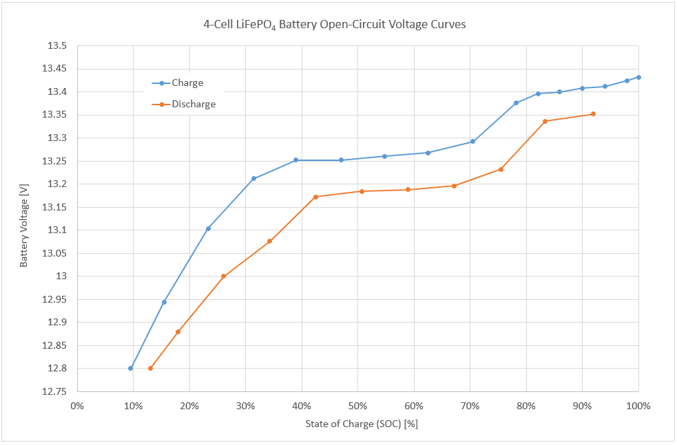
Attachment 120889
I don't have any good data specifically for OCV. This graph is for 100AH cells being charged/discharged at a constant C/5 or 20A rate. The OCV would obviously be somewhere between the two lines, and probably different depending on if the last action was charge or discharge.
This is a different curve though than the one a couple posts back. Not all cells are going to be the same. If you had these cells, trying to determine SOC based on voltage would be really difficult.
Sent from my iPad using Cruisers Sailing Forum
|
|
|
|
|
17-03-2016, 08:11
|
#5046
|
|
Registered User
Join Date: Dec 2011
Location: On the boat
Boat: DeFever 44
Posts: 292
|
Re: LiFePO4 Batteries: Discussion Thread for Those Using Them as House Banks
Attachment 120890
Better Upload
Sent from my iPad using Cruisers Sailing Forum
|
|
|
|
|
17-03-2016, 10:35
|
#5047
|
|
Marine Service Provider
Join Date: May 2011
Location: Cruising Mexico Currently
Boat: Gulfstar 50
Posts: 1,979
|
Re: Interesting Observations
Quote:
Originally Posted by OceanSeaSpray
SNIP %<
The curves above were recorded by a university in a lab with fully stabilised voltages, so they waited for ages before taking each reading etc.
At very small C-rates, like often found on marine banks, the current doesn't skew those values much. I find that I use the blue curve to assess charging in the upper range and the orange one to get an idea of how much I have left when the voltage starts dropping (but not while running alternators or heavy loads obviously, because of the effect of internal resistance again).
For example, when I see 13.1V under light discharge, I know I am about 60-65% down and it is highly reliable, much more than any Coulomb counter gizmo that needs constant resetting.
Similarly, when the solar panels are charging gently and the voltage has climbed to 13.4V, I know I am in the 80% SOC.
Last but not least, this is true regardless of capacity: it naturally tracks any capacity fade. |
Can you give us a pointer to the paper? It would be an interesting read.
Ages to let the cell voltage settle out. Define ages (hours, days, weeks?) Inquiring minds want to know.
Looks like good stuff with a lot to be learned from the graph alone.
|
|
|
|
|
17-03-2016, 10:52
|
#5048
|
|
Marine Service Provider
Join Date: Jan 2007
Location: Maine
Boat: CS-36T - Cupecoy
Posts: 3,197
|
Re: Interesting Observations
Quote:
Originally Posted by evm1024
Can you give us a pointer to the paper? It would be an interesting read.
Ages to let the cell voltage settle out. Define ages (hours, days, weeks?) Inquiring minds want to know.
Looks like good stuff with a lot to be learned from the graph alone.
|
I suspect it was extrapolated from this white paper/study: LiFePO4 Battery Performance Test Methods and Analysis, Energy
Title: LiFePO4 Battery Performances Testing and Analyzing for BMS
Author: Dr. Languang Lu
I have that paper on my hard drive but could not find a free .pdf on-line...
|
|
|
|
|
17-03-2016, 11:21
|
#5049
|
|
Marine Service Provider
Join Date: May 2011
Location: Cruising Mexico Currently
Boat: Gulfstar 50
Posts: 1,979
|
Re: Interesting Observations
Quote:
Originally Posted by Maine Sail
|
Thanks, a pdf can be found here: http://www.cse.anl.gov/us-china-work...0for%20BMS.pdf
So the graph on page 10 indicates that 3 hours will give a stable OCV within 1 mV of the 4 hour stable point.
Also, I found the reasons for different cell voltages on page 29 to be interesting.
Page 20 reinforces your (Mainsail's) assertion that the coulomb efficiency is near 100% (99.0 to 99.4% depending on the cycle number)
Lastly, I wonder what effect a small 100mA discharge rate has on the cell voltage. Does the cell voltage under this discharge track the OCV in time? What offset if it does track?
|
|
|
|
|
17-03-2016, 13:40
|
#5050
|
|
Marine Service Provider
Join Date: Aug 2013
Location: New Zealand
Boat: Custom 13m aluminium sloop
Posts: 287
|
Re: Interesting Observations
Quote:
Originally Posted by Maine Sail
|
It is correct, I quoted it where I published the plot. I loaded the graph from the slide in a CAD program and drew exactly on top of it to get an accurate scale of each data point and create a table. The graph I posted is an Excel plot for a 4-cell battery.
Good OCV curves are rare and quite hard to find, but they are most important because in reality our batteries are not charged and discharged at constant current from end to end and they sit idle at times.
I would expect small differences between battery models, but this plot is very typical of LiFePO4 chemistry in general. I can see the same relation with my Sinopoly cells with a secondary shelf at 13.4V when charging gently. Small currents don't change the picture by more than a few millivolts, but C/5 is not a small current at all.
To me, SOC is only interesting in the lower part when discharging and in the upper part when charging. I don't care about the flattish area, there is plenty of power left when I am there. If you cycle so quickly that it matters, then you need to measure, but auto-resetting the instrument is not normally such a big deal either then.
Generally speaking, I like the bank to offer a few days reserve capacity, so I get time to "find" some power and I cycle quite deeply and slowly. My solar system is not allowed to automatically recharge every day. Most of the time, it just makes up for the consumption and the battery sits idle until the evening.
Current efficiency is near 100% (it is the main reason why LFPs charge so much better, they waste nothing), but power efficiency is normally around 95% because the current must be supplied at a higher voltage for charging than it is retrieved at later.
Current efficiency is what matters to us, because we can always find a little more voltage.
__________________
"The case for elimination: the only equipment that never needs maintenance and never breaks down is the one you don't have on board."
|
|
|
|
|
17-03-2016, 14:26
|
#5051
|
|
Marine Service Provider
Join Date: Aug 2013
Location: New Zealand
Boat: Custom 13m aluminium sloop
Posts: 287
|
Re: Interesting Observations
Quote:
Originally Posted by evm1024
Thanks, a pdf can be found here: http://www.cse.anl.gov/us-china-work...0for%20BMS.pdf
So the graph on page 10 indicates that 3 hours will give a stable OCV within 1 mV of the 4 hour stable point.
Also, I found the reasons for different cell voltages on page 29 to be interesting.
Page 20 reinforces your (Mainsail's) assertion that the coulomb efficiency is near 100% (99.0 to 99.4% depending on the cycle number)
Lastly, I wonder what effect a small 100mA discharge rate has on the cell voltage. Does the cell voltage under this discharge track the OCV in time? What offset if it does track? |
It does track quite well and the offset is essentially Pack Resistance x Current.
When some meaningful current is flowing, each cell voltage gets skewed by the cell's own internal resistance and they can read different while in fact perfectly balanced. This is what makes shunting boards completely unusable in our type of application, they throw the balance out more than anything else. Crude voltage-based shunting can only be successful at very low current. Our partial charges at high current with alternators defeat this completely.
I had a go at developing these things here some time last year because they are important and it is also where the OCV plots are.
__________________
"The case for elimination: the only equipment that never needs maintenance and never breaks down is the one you don't have on board."
|
|
|
|
|
17-03-2016, 14:40
|
#5052
|
|
Marine Service Provider
Join Date: Jan 2007
Location: Maine
Boat: CS-36T - Cupecoy
Posts: 3,197
|
Re: Interesting Observations
Quote:
Originally Posted by OceanSeaSpray
It is correct, I quoted it where I published the plot.
|
I didn't see a reference here but know that paper as it is one of 100+ I have on my hard drive..
Quote:
Originally Posted by OceanSeaSpray
I loaded the graph from the slide in a CAD program and drew exactly on top of it to get an accurate scale of each data point and create a table. The graph I posted is an Excel plot for a 4-cell battery.
|
That explains why the graph confused me a bit. By your description I was able to find the paper on my hard drive and why I said "looks to be extrapolated from"..
Quote:
Originally Posted by OceanSeaSpray
To me, SOC is only interesting in the lower part when discharging and in the upper part when charging. I don't care about the flattish area, there is plenty of power left when I am there. If you cycle so quickly that it matters, then you need to measure, but auto-resetting the instrument is not normally such a big deal either then.
|
Absolutely but I have noted at discharge rates that are in the 0.02C range that the voltage hangs out higher longer then drops very rapidly.. At higher discharge rates the discharge curve looks more like the curves we are used to seeing. On my own bank our average discharge rate is about 0.02C or about 8A on a 400A bank. We rarely dip below 80% DOD but when i do and get close to 0% the drop has very little slope, hence staying at a max DOD of 80%..
Quote:
Originally Posted by OceanSeaSpray
Generally speaking, I like the bank to offer a few days reserve capacity, so I get time to "find" some power and I cycle quite deeply and slowly. My solar system is not allowed to automatically recharge every day. Most of the time, it just makes up for the consumption and the battery sits idle until the evening. |
We do exactly the same and its why our bank is so big. We can go many days without so much as thinking about even turning on the solar or engine. As I did to about 35% SOC I may flip on the array just to buy a bit more time or another day or more..
Quote:
Originally Posted by OceanSeaSpray
Current efficiency is near 100% (it is the main reason why LFPs charge so much better, they waste nothing), but power efficiency is normally around 95% because the current must be supplied at a higher voltage for charging than it is retrieved at later.
Current efficiency is what matters to us, because we can always find a little more voltage.
|
Absolutely! I have never been concerned with the power efficiency, all batteries need more voltage to charge, but rather the charge current efficiency of what goes in to what is stored and comes out. This is usually above 99.5% +/- efficient and I have measured it carefully over many hundreds of cycles to the best of my test equipment and data loggers capabilities. Interestingly enough AGM lead acid batteries are darn near 98%+/- efficient during bulk charging but that last 5% can be as bad as 35% of each Ah delivered actually being stored.... 
|
|
|
|
|
17-03-2016, 14:44
|
#5053
|
|
Marine Service Provider
Join Date: May 2011
Location: Cruising Mexico Currently
Boat: Gulfstar 50
Posts: 1,979
|
Re: Interesting Observations
Quote:
Originally Posted by OceanSeaSpray
It does track quite well and the offset is essentially Pack Resistance x Current.
When some meaningful current is flowing, each cell voltage gets skewed by the cell's own internal resistance and they can read different while in fact perfectly balanced. This is what makes shunting boards completely unusable in our type of application, they throw the balance out more than anything else. Crude voltage-based shunting can only be successful at very low current. Our partial charges at high current with alternators defeat this completely.
I had a go at developing these things here some time last year because they are important and it is also where the OCV plots are. |
Thanks for the link - A great encapsulation of LiFePO4 information and "required" reading.
Question - What offset (assuming the curves are the same...) in voltage would expect to see between straight LiFePO4 cells and Thunder/Winston LiYFePO4 cells? (for the OCV graphs at least)
|
|
|
|
|
17-03-2016, 15:17
|
#5054
|
|
Marine Service Provider
Join Date: Aug 2013
Location: New Zealand
Boat: Custom 13m aluminium sloop
Posts: 287
|
Re: Interesting Observations
Quote:
Originally Posted by evm1024
Question - What offset (assuming the curves are the same...) in voltage would expect to see between straight LiFePO4 cells and Thunder/Winston LiYFePO4 cells? (for the OCV graphs at least)
|
I really don't know. There isn't much (any?) published lab data available for LiYFePO4 chemistry and I never came across these cells so far.
Cold temperature performance is supposed to be better with yttrium and I would expect a number of these graphs to look a bit different.
I believe the yttrium further facilitates lithium intercalation... but there is no current when OCV is measured, it is a measure of the distribution of the lithium. The curve could be very similar. I would try adopting it and comparing with Coulomb counting at the "turning points".
When I did that with straight LiFePO4, the correlation was excellent and if it wasn't, then it was because the counter was out of sync.
__________________
"The case for elimination: the only equipment that never needs maintenance and never breaks down is the one you don't have on board."
|
|
|
|
|
17-03-2016, 15:46
|
#5055
|
|
Marine Service Provider
Join Date: May 2011
Location: Cruising Mexico Currently
Boat: Gulfstar 50
Posts: 1,979
|
Re: Interesting Observations
Quote:
Originally Posted by OceanSeaSpray
Generally speaking, I like the bank to offer a few days reserve capacity, so I get time to "find" some power and I cycle quite deeply and slowly. My solar system is not allowed to automatically recharge every day. Most of the time, it just makes up for the consumption and the battery sits idle until the evening.
|
Much like I do (disclaimer not a full time cruiser as of yet just up to a few weeks at a time)
I try to cycle around 50% SOC. The math is interesting if you try to factor in everything but in concept is much more simpler.
Discharge(total) = Charge(total) for any given cycle time.
This ignores any losses in charge or discharge which is OK for the concept. It just says that you need to replace the used capacity such that you can use that capacity again in the next cycle.
Also:
Capacity(bank) / 2 + Discharge(total) / 2 = SOC(upper)
Capacity(bank) / 2 - Discharge(total) / 2 = SOC(lower)
Which says that for a 50% average SOC you will cycle between half the discharge total above and below the average SOC. So, for a 400 AH bank the you intend to have at 50% on average then 1/2 of 100 AH per cycle = 50 AH thus the cycle will go between 250 AH (400/2 + 100/2) and 150 AH (400/2 - 100/2) or 250/400= 62.5% SOC and 150/400 = 37.5% SOC.
This is a pretty simple model. Complication factors are the differences in rates of discharge at various times in the charge/discharge cycle time (day vs night for example).
A simple procedure is to note the SOC at the point that you are ready to start charging and then to charge until you hit the SOC as much above 50% as you were below. 100% - 37.5% = 67.5%
Of course measuring SOC with a coulomb counter gets out of sync and the offset from 50% SOC get greater with time which requires resyncing the counter and the bank to 100% SOC (or a reasonable SOC near 100%) and letting it drift down to 50% SOC average over the next few days.
Sorry to ramble on here - And of course this is a great bunch of generalities that speak of one strategy for hovering around 50% SOC...
|
|
|
|
|
|
| Thread Tools |
Search this Thread |
|
|
|
| Display Modes |
Rate This Thread |
 Linear Mode Linear Mode
|
|
 Posting Rules
|
You may not post new threads
You may not post replies
You may not post attachments
You may not edit your posts
HTML code is Off
|
|
|
|
Advertise Here

 Recent Discussions Recent Discussions |
|
|
|
|
|
|
|
|
|
|
|
|
|
|
|
|
|
|
|
|
|
|
|
|
|
Vendor Spotlight |
|
|
|
|
|
|
|
|
|


