 |
 09-10-2018, 05:13
|
#1
|
|
Registered User

Join Date: Feb 2015
Posts: 1,227
|
Jacking up the alternator voltage
Has anyone jacked up their alternator voltage, and if so, what mods had to be made?
I'm wondering, as an example, about running a 24V LN alternator at 48V. And let's assume I'll only draw the same max power, not more, do I'll be doubling the voltage and cutting the current in half. And let's assume external regulation, and that I have a 48V regulator.
What are the issues and what mods need to be made? The obvious spots are:
- Can the rectifier diodes handle the higher voltage? In practice a 48V system will run at up to 60V, so the diodes need to be rated for probably 70 to maybe 90V? Even higher would be better, but I have no idea what's available. Are the existing diodes sufficient?
- Can the winding insulation handle the higher voltage? This one I have no idea. I don't know what sort of voltage rating the insulation on typical windings has, and what it's rated for.
- What happens to the field control? At 24V, full field voltage equals full rated output. Let's say that's 100A @ 24V. What happens if you double the voltage? Does 48V field still equal full output? And is that the same wattage output, i.e. 50A, or is that the same current, i.e. 100A? Or do you need to limit field voltage to 1/2 or 1/4 of full voltage?
Anyone ever tried this?
|

|

|
|
09-10-2018, 06:45
|
#2
|
|
Registered User
Join Date: Oct 2011
Boat: Valiant 42
Posts: 6,008
|
Re: Jacking up the alternator voltage
I haven't tried it but it is unlikely to work well. You have identified several potential problems. In addition, the number of turns on the rotor determines the maximum output voltage along with the field current. Since space inside an alternator is a premium the designer will not likely have put in twice the number of turns of rotor wire as needed for 24V. Similar issue will exist in the field side. Brushes may not handle the extra field current. And you will need more field current than for 24V.
Magnet wire has a voltage rating of about 20-30V. Since the wires are laid down in layers the voltage that matters is the turn to turn voltage which your idea will double. That will chew up most all the safety factor in most magnet winding designs.
The field current actually controls how much current flows in the rotor, not voltage, up to some maximum determined by the number of rotor turns and RPM. The battery determines the voltage for a given field current. That's why the regulator has to monitor battery voltage. And why you should never disconnect the battery from a running alternator.
There is no free lunch. It will make some power but I doubt you can get more than 25% of the 24V current when attempting to get 48V. So best estimate would be about 50% of rated power. And to get that might over stress the field circuit.
|
|
|
|
|
09-10-2018, 07:59
|
#3
|
|
Registered User
Join Date: Mar 2016
Boat: Lagoon 440
Posts: 736
|
Re: Jacking up the alternator voltage
I would bet a 12V alt can feed a 24V or 48V battery no problem as long as the field remains 12V. The bridge rectifier seems to be usually rated for AC input, not DC output, and it's usually higher than 300V AFAIK. You should then get a bit more than 100% rated power (W) ouput as the rectifier will suffer less losses at 1/2 Amps and 2x Voltage.
And I would bet you would very quickly fry a 12V alt with a 24V field.
But I am following the thread for a better explanation from someone who knows for sure 
|
|
|
|
|
09-10-2018, 12:41
|
#4
|
|
֍֎֍֎֍֎֍֎֍֎
Join Date: Apr 2006
Posts: 15,136
|
Re: Jacking up the alternator voltage
You shouldn't need to "jack up" alternator voltage. That's the regulator's job. And even if you have a fixed internal regulator, you "should" have a "3-wire" system, where the alternator has a voltage sense lead that measures voltage AT the batteries, and automatically jacks it up to a proper charging voltage based on lead acid wet batteries.
If you have a "1-wire" system where the voltage sense lead has been tied back to the output directly (a cheap way to deal with dual-bank systems without switching the one lead to them) then of the answer is to fix the cheapo kludge.
Jacking up a functional system should just accomplish boiling out the batteries more. Jacking it up to compensate for other shortcomings, is just patching a kludge instead of fixing the problems, isn't it?
|
|
|
|
|
09-10-2018, 13:43
|
#5
|
|
Registered User
Join Date: May 2015
Posts: 11
|
Re: Jacking up the alternator voltage
The alternator should be able to handle 24 or 48 volts without breaking down. You can apply voltage to your field windings and see what voltage it can put out unregulated by bypassing the regulator. The regulator works on the field/rotor voltage, the output comes from the stator. This is so the regulator is switching much lower current than the alternator output.
If you are really clever you can change the value of the variable resistor (voltage adjustment screw on regulator) to get a different voltage output range.
In these extra low voltage applications it is usually higher current that burns out components, not voltage (Sensitive electronics are different). All your loads and batteries will need to be changed to the higher voltage rating as well as it will all get too hot and you will have issues there.
|
|
|
|
|
09-10-2018, 14:12
|
#6
|
|
Registered User
Join Date: Nov 2006
Location: San Francisco Bay
Boat: Fantasia 35
Posts: 1,251
|
Re: Jacking up the alternator voltage
|
|
|
|
|
09-10-2018, 15:08
|
#7
|
|
Senior Cruiser

Join Date: May 2013
Location: Oregon to Alaska
Boat: Wheeler Shipyard 83' ex USCG
Posts: 3,509
|
Re: Jacking up the alternator voltage
I use GM CS-144 alternators on all my engines because they are common and cheap. The smallest version puts out 140 amps at 12v, and 35 amps at 48v. At engine idle the CS-144 is already putting out 70 amps @ 12v with a 4:1 pulley. One CS-144 was modified (bypass the internal voltage regulator) to charge my 48v house banks. Originally I controlled it by hand but now I use an outside regulator. The voltage regulator is what controls the output voltage. If you search the web, ebay, etc., there are companies that make 48v external regulators. They can explain it better than I can. I went to a 48v alternator so when running the mains I keep the house bank charged while using the inverter and not have to run a generator. I went to a 48v bank because of better choices in inverters and much smaller cabling is needed compared to 12v.
The CS-144 can be modified for higher power output and are the base for several aftermarket alternators. A new 140 amp is about $90 on ebay and used ones about $30. There are 2-300 amp versions on ebay.
|
|
|
|
|
09-10-2018, 15:14
|
#8
|
|
Registered User
Join Date: Oct 2011
Boat: Valiant 42
Posts: 6,008
|
Re: Jacking up the alternator voltage
Quote:
Originally Posted by elscotto

The alternator should be able to handle 24 or 48 volts without breaking down. You can apply voltage to your field windings and see what voltage it can put out unregulated by bypassing the regulator. The regulator works on the field/rotor voltage, the output comes from the stator. This is so the regulator is switching much lower current than the alternator output.
If you are really clever you can change the value of the variable resistor (voltage adjustment screw on regulator) to get a different voltage output range.
In these extra low voltage applications it is usually higher current that burns out components, not voltage (Sensitive electronics are different). All your loads and batteries will need to be changed to the higher voltage rating as well as it will all get too hot and you will have issues there. |
Careful! If you put 48V on the field of a 24V alternator look out for a fire. Best leave this idea for another day. And then wait until the day after that.
If you put about a 5 ohm ballast resistor in series with the field wire then it probably wont burn up the alternator. But the ballast resistor will be pretty hot. About 150 watts or more. Again, this is not something for a shade tree mechanic/electrician.
|
|
|
|
|
10-10-2018, 10:39
|
#9
|
|
Registered User
Join Date: Apr 2007
Location: Australia
Boat: Island Packet 40
Posts: 6,452
|
Re: Jacking up the alternator voltage
If you intend pulling the same wattage from the stator coils and ,as you say halving the ampage, they should run a lot cooler. However, since the rotor will require higher voltage and hence current it will run hotter. However, the rotor excitation current is a lot less than the stator coil currents so the total heat generated by the alternator should be far lower.
I'd do a suck it and see trial with manually controlled voltage output and see how hot it got, it's heat cooking the insulation which generally destroys alternators, if it starts to get too hot discontinue the experiment.
|
|
|
|
|
10-10-2018, 13:32
|
#10
|
|
cruiser
Join Date: Jan 2017
Boat: Retired from CF
Posts: 13,317
|
Re: Jacking up the alternator voltage
Aren't nominal 48V alternators available?
If not OTS , tons of quality mod-custom winders out there.
|
|
|
|
|
10-10-2018, 22:04
|
#11
|
|
Registered User
Join Date: Feb 2015
Boat: Land bound, previously Morgan 462
Posts: 1,991
|
Re: Jacking up the alternator voltage
As written by TransmitterDan, "the number of turns on the rotor determines the maximum output voltage along with the field current."
That's all you need to know as far as telling you that if you want a 48V output, you should buy a 48V alternator. Conceivably you could rewind a 12V alternator with smaller wire (1/4 the cross section area) and 4x the number of turns, and replace the diodes with ones rated for 4x the voltage.
Pretty hard to use 48V with most boat equipment even though it's clear that 48V would be more efficient for wiring. 48V is getting to the almost dangerous shock potential for humans especially around salt water.
|
|
|
|
|
10-10-2018, 22:55
|
#12
|
|
Registered User
Join Date: Aug 2011
Location: Petersburg, AK
Boat: Outremer 50S
Posts: 4,229
|
Re: Jacking up the alternator voltage
Somebody's already done the work  This is from a study looking at current alternator designs and moving cars to a 42V bus (something that still hasn't happened).
The short story, with a 12V-designed alternator you need much higher shaft speeds to maintain the magnetic field so that you don't get voltage collapse.
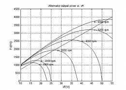
A 12V alternator can produce up to ~23V at 1800 shaft rpm, but to get to 55V (which would be required for a 48V system) a minimum shaft speed of 5000 rpm was required.
The testing was done with a bog-standard claw-pole automotive alternator, other beasts may respond differently.
|
|
|
|
|
11-10-2018, 08:29
|
#13
|
|
Registered User
Join Date: Feb 2015
Posts: 1,227
|
Re: Jacking up the alternator voltage
Quote:
Originally Posted by Dsanduril
Somebody's already done the work This is from a study looking at current alternator designs and moving cars to a 42V bus (something that still hasn't happened).
The short story, with a 12V-designed alternator you need much higher shaft speeds to maintain the magnetic field so that you don't get voltage collapse.
Attachment 178785
A 12V alternator can produce up to ~23V at 1800 shaft rpm, but to get to 55V (which would be required for a 48V system) a minimum shaft speed of 5000 rpm was required.
The testing was done with a bog-standard claw-pole automotive alternator, other beasts may respond differently. |
Which confirms the previous comment that rewinding the rotor is really needed.
|
|
|
|
|
| Thread Tools |
Search this Thread |
|
|
|
| Display Modes |
Rate This Thread |
 Linear Mode Linear Mode
|
|
 Posting Rules
|
You may not post new threads
You may not post replies
You may not post attachments
You may not edit your posts
HTML code is Off
|
|
|
|
Advertise Here

 Recent Discussions Recent Discussions |
|
|
|
|
|
|
|
|
|
|
|
|
|
|
|
|
|
|
|
|
|
|
|
|
|
Vendor Spotlight |
|
|
|
|
|
|
|
|
|


