 |
|
 29-05-2015, 00:09
|
#1
|
|
Registered User

Join Date: Apr 2015
Location: Melbourne Australia
Boat: John Pugh Steel 26ft
Posts: 1
|
Duplex fuses in circuits?
Hi all. My John Pugh design 26ft steel yacht has 2 fuses in each electric circuit. A typical circuit is as follows:
Battery positive, battery positive selector switch, positive buss, amp meter, fuse, switch, device circuit is for, fuse, negative buss, negative battery selector switch, negative battery terminal.
As you can see, there are 2 battery selector switches (positive and negative HV cables) as well as 2 fuses in each circuit. Is this related to the fact that she is a steel hull boat?
|

|

|
|
29-05-2015, 02:22
|
#2
|
|
Moderator

Join Date: Jul 2007
Boat: Bestevaer.
Posts: 14,678
|
Re: Duplex fuses in circuits?
Welcome to the forum.
Dual pole (both positive and negative) switches and circuit breakers are the better way to wire a metal boat. In fact, it is also better for a non metal boat, but is not generally worth the cost/trouble.
Some commercial boats are required to fit duel pole main battery switches even if they are built from fibreglass.
Generally this is done seamlessly with battery switches and circuit breakers that have a single switch, but break both the positive and negative circuit.
This battery switch for example looks, and operates like an ordinary single pole battery switch, but it switches both the positive and negative wires at the same time. It sounds like the person that built the boat could not source this type of switch and has used two single pole units instead. Other than the nuisance I don't see any problem.

|
|
|
|
|
29-05-2015, 03:18
|
#3
|
|
Registered User
Join Date: Feb 2011
Location: Poland, EU
Boat: crew on Bavaria 38 Cruiser
Posts: 654
|
Re: Duplex fuses in circuits?
Quote:
Originally Posted by noelex 77

Dual pole (both positive and negative) switches and circuit breakers are the better way to wire a metal boat. In fact, it is also better for a non metal boat, but is not generally worth the cost/trouble.
|
Could you perhaps list a failure mode which is addressed by the dual fuse/breaker setup and which is not addressed by a single breaker setup? Not criticising, just interested.
|
|
|
|
|
29-05-2015, 06:52
|
#4
|
|
Moderator
Join Date: Jul 2007
Boat: Bestevaer.
Posts: 14,678
|
Re: Duplex fuses in circuits?
Quote:
Originally Posted by mrm
Could you perhaps list a failure mode which is addressed by the dual fuse/breaker setup and which is not addressed by a single breaker setup?
|
A good question. Please understand the subject is complex. To boil it down to simple, but technically accurate explanations requires a deep understanding that is beyond my level of knowledge. However, I will try with an example.
The main gain of a dual pole system is in the reduction of stray current corrosion. Unlike other forms of corrosion, stray current corrosion can be very rapid. This is a much greater risk for a metal boat, although something like a saildrive on a fibreglass boat can be destroyed in a very short time from this type of problem.
For conventional single pole systems the negative supply is always connected to every wire even if the circuit is off (unless the battery is disconnected).
The negative is often thought of as "ground" but in DC system this means little. In fact, the electrons flow from the minus pole to the positive pole not the other way around, as first thought when the terms were initially devised.
We commonly think of the negative wires sitting at the same potential as each other, but in practice there are voltage differences. Even before any fault has developed wires in a well installed system are sized for 0.2 V drop on each pole. Higher differences are commonly seen.
So in a single pole system the negative supply is connected to all equipment all the time. Some of this equipment may be in contact with seawater. The engine and ruddershaft are common culprits. This is because the engine in a single pole system is permanently connected to the negative supply and usually connected to seawater via the shaft. The ruddershaft is a culprit because the autopilot is frequently poorly isolated from carbon buildup.
When the engine is stopped with a single pole system the large battery cables suppling the engine with little current will mean this will sit very close to the potential of the battery negative. The autopilots ground wire will fluctuate in voltage depending on the current drawn size of wires etc. Even low voltage differences can cause significant corrosion. Two metals emersed in an electrolite not at same potential means one will corrode.
This is only one scenario, but this occurs without any real fault (other than some carbon build up in the autopilot drive). It ignores bonding and an isolated drive system, but these are not on all boats.
Turning off the negative and positive supply at each switch and the engine block reduces potential problems. Metal boats often also have a test system to ensure that the is no negative or positive connection to any of the underwater metal.
Note that in the above I have not considered a real fault like a partially chafed wire in contact with a metal part of the hull underwater. If this is a negative wire there will be no indication of the fault. Even if it is a positive wire, the high resistance will not blow a fuse. Here very high voltage differences can be generated.
|
|
|
|
|
29-05-2015, 10:28
|
#5
|
|
Registered User
Join Date: Oct 2014
Location: Bay of Fundy,Grand Manan,N.B.,Canada N44.40 W66.50
Boat: Mascot 28 pilothouse motorsailer 28ft
Posts: 3,256
|
Re: Duplex fuses in circuits?
In my experience as Marine Electronic Tech over 30+ yrs,I have encountered a few weird situations re-negative wires.
When Loran C was popular,some of the older units-Furuno,Comnav,etc used to use a fuse in both neg & pos supply leads.IIRC Furuno,& a few top end VHF mfgrs carried this on into the early GPS era. Been retd from the business for some yrs,so not up on current units.
Two instances of why this was good practice,especially on products that had antennae mounted on metal masts:
(1) A nav light pos. lead chafes thru to an ungrounded(or poorly grounded)metal mast-the current finds a path thru the eqpt antenna,follows the lead-in(coax braid,etc) to the Eqpt looking for Neg. If Neg is fused,usually it pops & NP. Not fused,Neg path will fry the lead-in or ckt bd,or RF ground lead from Eqpt cabinet to earth -ground plate,eng.block,shaft,prop.
If not enough current to fry the neg. path open,then you have a pos potential permanently applied to your earthing gear as listed above,with serious electrolysis. Even worse on a metal or soaked up wood vessel.
(2) lightening or heavy "static" from super charged atmosphere-will try to follow all earth paths to water,including lead-ins.
Good reason why every metal item-mast,rails,etc-that have ants,lights,electrics- mounted on them,should have a heavy,well maintained earth wire,connected to the vessels engine block.I say engine block because it is normally earthed via shaft & prop.If you have a "drive saver",it should be jumpered with a strap,so your engine earth is maintained IMHO.
Battery neg is normally connected to engine block by starter cable,though I have encountered some (Detroit Diesel for one) that the starter motor is internally isolated from block,Neg bat, conn'd to floating Neg starter term,with the optional starter Neg to eng. block factory jumper not installed.This inevitably lead to the control cables,mech tach cable,etc
becoming a Neg bat path & frying or causing various problems.
Note: Isolated starters were for counter rotating twin engines-you can wire +/- starter terms either way allowing mfgr to use same motor for left & right turning engs.
It is really difficult to isolate engines & other large chunks of metal from earth on a wet boat.Better to embrace this earthing,& wire rest of boat accordingly IMHO.
__________________
 My personal experience & humble opinions-feel free to ignore both
.
|
|
|
|
|
29-05-2015, 10:36
|
#6
|
|
Registered User
Join Date: Dec 2013
Location: SF Bay
Boat: 36' Hartog ketch
Posts: 33
|
Re: Duplex fuses in circuits?
Can you point to a source that would show how to implement a system like that, where other items like charger/inverters are in the mix? The google searches for the specific switch you mention are not helpful so far.
Thanks 
|
|
|
|
|
29-05-2015, 12:59
|
#7
|
|
Moderator
Join Date: Jul 2007
Boat: Bestevaer.
Posts: 14,678
|
Re: Duplex fuses in circuits?
Quote:
Originally Posted by ThresherMan
Can you point to a source that would show how to implement a system like that, where other items like charger/inverters are in the mix?
|
In simple terms the battery leads to battery switch that switches on and off both the positive and negative circuits. (Instead of just the positive supply). This leads to switchboard with dual pole circuit breakers that will once again switch and respond to an over current situation on both the positive and negative circuits. (Instead of leaving the negative connected all the time). These are basically two circuit breakers joined together during manufacturing, although this is not always obvious from the external appearance.
The engine is fitted with an isolated alternator (many, or even most, marine alternators are isolated as standard) with two wire senders. An isolated starter is sometimes used, but more commonly the engine is briefly ground during the few seconds of starting then the negative supply is removed from the block. This enables the use of a standard starter. An automatic system to do this to the engine is simple.
|
|
|
|
|
29-05-2015, 13:03
|
#8
|
|
Registered User
Join Date: Apr 2015
Location: Ladner, Delta, British Columbia Canada.
Boat: Coast 30
Posts: 374
|
Re: Duplex fuses in circuits?
Deblen...for some of us who are electrically challenged, myself especially I would have learned more from your wise council if you had not used so many abbreviations that I could not quite understand.
I have a cold moulded african hardwood hull with a fabricated steel case keel fin filled with 2,700 Lbs of lead bolted to the bottom of it.
there is an earth wire from the port side chain plate to the keel which I presumed is intended to protect the rig from lightening strikes.... should I be running a negative earth wire from all my electrical system to this connection?
|
|
|
|
|
29-05-2015, 14:46
|
#9
|
|
Marine Service Provider
Join Date: Sep 2011
Location: California
Boat: Alerion Express 38 Yawl (former)
Posts: 468
|
Re: Duplex fuses in circuits?
Quote:
Originally Posted by noelex 77
Welcome to the forum.
Dual pole (both positive and negative) switches and circuit breakers are the better way to wire a metal boat. In fact, it is also better for a non metal boat, but is not generally worth the cost/trouble.
Some commercial boats are required to fit duel pole main battery switches even if they are built from fibreglass.
Generally this is done seamlessly with battery switches and circuit breakers that have a single switch, but break both the positive and negative circuit.
This battery switch for example looks, and operates like an ordinary single pole battery switch, but it switches both the positive and negative wires at the same time. It sounds like the person that built the boat could not source this type of switch and has used two single pole units instead. Other than the nuisance I don't see any problem.
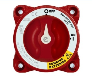 |
OK, please don't do this. This battery switch is not intended to switch positive and negative circuits that the same time. It has an "All" position, in yellow, which would directly connect the positive and negative terminals of the battery bank(s) with catastrophic results.
This is a wonderful switch when separating your starting battery loads and your house loads, and it works extremely well with a battery combiner or Automatic Charge Relay (also from Blue Sea Systems). It has a place on a boat, but not the place described above.
Chuck Hawley
|
|
|
|
|
29-05-2015, 15:05
|
#10
|
|
Registered User
Join Date: Oct 2014
Location: Bay of Fundy,Grand Manan,N.B.,Canada N44.40 W66.50
Boat: Mascot 28 pilothouse motorsailer 28ft
Posts: 3,256
|
Re: Duplex fuses in circuits?
Quote:
Originally Posted by noelex 77
In simple terms the battery leads to battery switch that switches on and off both the positive and negative circuits. (Instead of just the positive supply). This leads to switchboard with dual pole circuit breakers that will once again switch and respond to an over current situation on both the positive and negative circuits. (Instead of leaving the negative connected all the time). These are basically two circuit breakers joined together during manufacturing, although this is not always obvious from the external appearance.
The engine is fitted with an isolated alternator (many, or even most, marine alternators are isolated as standard) with two wire senders. An isolated starter is sometimes used, but more commonly the engine is briefly ground during the few seconds of starting then the negative supply is removed from the block. This enables the use of a standard starter. An automatic system to do this to the engine is simple. |
As I said in my previous post,my experience has shown that it is very difficult to keep the engine,starter,alternator,mast & any other metal objects that have electrical equipment bolted to them, totally isolated & floating electrically with no + or - potential of any amount. Especially in salt water/salt air & on < 75ft or less yachts that we are talking about.
The reason I say this is because these size vessels don't usually have a marine engineer aboard to supervise or do electrical work.They get worked on by people of various abilities,beliefs & practices-including the owner &
friends.
IMHO these vessels do not have very complicated electrical systems & KISS should be the rule.
Yes-they should be wired to ABYC or CE standards.If you don't know these standards,it's not just a matter of legal responsability,it's yours & your families,etc. lives at stake.
Don't complicate unnecessarily. If you are worried,& there seem to be many,many non-electrical posters that are worried,hire a well respected marine electrician to check your boat out.Get it checked by another one,if you suspect the first is selling you non-reqd. upgrades/repairs.
For a few hundred bucks,you can be safe & have piece of mind.
There are all kinds of self appointed experts who have read a particular book or three,but nothing beats real world experience.
Once you have had things professionally checked,I believe you can learn how to run wires safely,make good connections,etc if you are so inclined & are willing to study the many good references on how to do the physical part.
Leave the theory to those that have actually been there/done that.
Your choice / Len
__________________
My personal experience & humble opinions-feel free to ignore both
.
|
|
|
|
|
29-05-2015, 15:48
|
#11
|
|
Registered User
Join Date: Oct 2014
Location: Bay of Fundy,Grand Manan,N.B.,Canada N44.40 W66.50
Boat: Mascot 28 pilothouse motorsailer 28ft
Posts: 3,256
|
Re: Duplex fuses in circuits?
Quote:
Originally Posted by coastalexplorer
Deblen...for some of us who are electrically challenged, myself especially I would have learned more from your wise council if you had not used so many abbreviations that I could not quite understand.
I have a cold moulded african hardwood hull with a fabricated steel case keel fin filled with 2,700 Lbs of lead bolted to the bottom of it.
there is an earth wire from the port side chain plate to the keel which I presumed is intended to protect the rig from lightening strikes.... should I be running a negative earth wire from all my electrical system to this connection? |
Sorry about the abbreviations-habit I guess & I'm a hunt & peck very slow typist.
If you have any questions on what I was abbreviating,just ask on here or private message.
Note: I use the term "earth" to denote the water around your boat,or a metal rod driven into the earth near your boat when docked.
This is to avoid the use of the term "ground",which has several questionable meanings among the general public,the worst of which is that the vessels ground is always at the same voltage (0 volts) as earth.This is not always true.
I use "negative" (neg or -) to denote the negative terminal of the battery & the negative wires going from batteries to electrical equipment.
I use "positive" (pos or +) to denote the positive term. of the bat. & the wires going from batteries to elec. eqpt.
(see how I'm sneaking some abbr. in there  )
I will leave AC wiring out for now.
You have an ideal setup for an earthing point-that big metal keel.
The heavy wire run from chain plates to keel bolt is to earth the mast & stays against lightening strike. The theory is that lightening takes the path of least resistance from mast to water,if you are struck.
It would be good if you ran an 8 gauge wire from your neg bat term to a keel bolt. This will connect the negative wiring in your boat to earth,& help eliminate potential corrosion & other problems.
That is about as far as i will go as I don't know your boat.
Cheers/ Len
__________________
My personal experience & humble opinions-feel free to ignore both
.
|
|
|
|
|
29-05-2015, 16:02
|
#12
|
|
Registered User
Join Date: Jun 2009
Location: Elyse is in New Zealand
Boat: Amel Super Maramu 2000
Posts: 589
|
Re: Duplex fuses in circuits?
On Amel boats the battery negative is not connected to "ground" - every metal part that is in touch with seawater has a "ground" wire connected to a common point (a copper strap on a keelbolt) which is then connected to zinc anodes on the rudder. The battery negative is NOT connected to this ground. The alternator is isolated from the engine and the starter is isolated by two start solenoids, one on the positive side and one on the negative sides so the negative is only connected to ground for a few seconds when starting the engine, same with the genset.
All the DC circuit breakers are single pole in the positive circuit.
There are two large switches in the battery compartment, one on the positive side and one on the negative side.
This seems to me to be a very good arrangement.
I don't see the need for having fuses/breakers in the negative supply circuits.
|
|
|
|
|
29-05-2015, 16:21
|
#13
|
|
Registered User
Join Date: Mar 2010
Location: Annapolis MD
Boat: Building a Max Cruise 44 hybrid electric cat
Posts: 3,199
|
Re: Duplex fuses in circuits?
Can single pole breakers be connected at the switch to form double pole breakers? I have a load of good single pole and don't want to have to replace with double pole when I rewire. Double poles look like two stuck together and a bushing on the handle.
I can't see the fault in this, but maybe there is something I'm missing.
Matt
|

|
|
|
29-05-2015, 17:36
|
#14
|
|
Registered User
Join Date: Oct 2014
Location: Bay of Fundy,Grand Manan,N.B.,Canada N44.40 W66.50
Boat: Mascot 28 pilothouse motorsailer 28ft
Posts: 3,256
|
Re: Duplex fuses in circuits?
Quote:
Originally Posted by Albro359
On Amel boats the battery negative is not connected to "ground" - every metal part that is in touch with seawater has a "ground" wire connected to a common point (a copper strap on a keelbolt) which is then connected to zinc anodes on the rudder. The battery negative is NOT connected to this ground. The alternator is isolated from the engine and the starter is isolated by two start solenoids, one on the positive side and one on the negative sides so the negative is only connected to ground for a few seconds when starting the engine, same with the genset.
All the DC circuit breakers are single pole in the positive circuit.
There are two large switches in the battery compartment, one on the positive side and one on the negative side.
This seems to me to be a very good arrangement.
I don't see the need for having fuses/breakers in the negative supply circuits. |
OK-Your pos wire to your mast mounted Steaming(Masthead) light chafes & connects to mast.Your mast is now +12V,as is every other piece of metal,including the rudder zincs,since they are all connected to that copper strap on keel bolt.
Will the Masthead light breaker pop? Why? What path does the current take to get from these +12V components,to the battery negative,because that is where the current has to go to make a circuit & blow the breaker/fuse?
Next-What happens if the same short to mast is high resistance,due to passing thru some corrosion or whatever? The resultant voltage on mast,etc. is small,but still a voltage applied to surrounding water.
Maybe I'm missing something? / Cheers/ Len
__________________
My personal experience & humble opinions-feel free to ignore both
.
|
|
|
|
|
29-05-2015, 17:41
|
#15
|
|
Registered User
Join Date: Oct 2014
Location: Bay of Fundy,Grand Manan,N.B.,Canada N44.40 W66.50
Boat: Mascot 28 pilothouse motorsailer 28ft
Posts: 3,256
|
Re: Duplex fuses in circuits?
Quote:
Originally Posted by funjohnson
Can single pole breakers be connected at the switch to form double pole breakers? I have a load of good single pole and don't want to have to replace with double pole when I rewire. Double poles look like two stuck together and a bushing on the handle.
I can't see the fault in this, but maybe there is something I'm missing.
Matt
|
Yes.
If you want to fool proof it,drill a small hole in the handles & install a cotter (split)pin thru the pos. & corresponding neg. breaker mounted one over the other.Both will flip at same time. / Len
__________________
My personal experience & humble opinions-feel free to ignore both
.
|
|
|
|
|
|
| Thread Tools |
Search this Thread |
|
|
|
| Display Modes |
Rate This Thread |
 Linear Mode Linear Mode
|
|
 Posting Rules
|
You may not post new threads
You may not post replies
You may not post attachments
You may not edit your posts
HTML code is Off
|
|
|
|
Advertise Here

 Recent Discussions Recent Discussions |
|
|
|
|
|
|
|
|
|
|
|
|
|
|
|
|
|
|
|
|
|
|
|
|
|
Vendor Spotlight |
|
|
|
|
|
|
|
|
|


 Alan S.V. Elyse


