 |
|
 02-06-2012, 03:52
|
#16
|
|
Registered User

Join Date: Feb 2010
Posts: 250
|
Re: Battery Cabling for Parallel Bank
Maine Sail,
So what configuration would be the best setup in Pete7's post, based on your experience with testing various battery setups? I just replaced my batteries this year, and I want to do what I can to get them to last as long as possible.
|

|

|
|
02-06-2012, 05:02
|
#17
|
|
Marine Service Provider
Join Date: Jan 2007
Location: Maine
Boat: CS-36T - Cupecoy
Posts: 3,197
|
Re: Battery Cabling for Parallel Bank
Quote:
Originally Posted by slowshoes

Maine Sail,
So what configuration would be the best setup in Pete7's post, based on your experience with testing various battery setups? I just replaced my batteries this year, and I want to do what I can to get them to last as long as possible. |
I've never come across any boat wired to the Smart Gauge Method #3 version (Image Courtesy Smart Gauge)
Smart Gauge Method #3
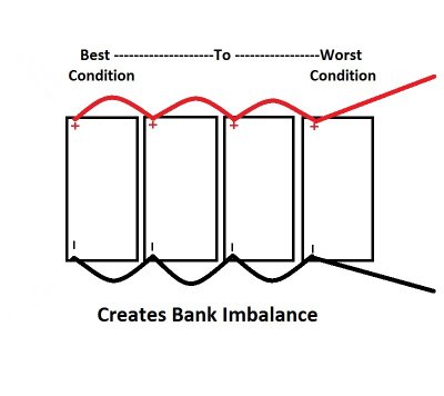
I have however seen many banks end connected like this:
End Connected:
And cross connected like this:
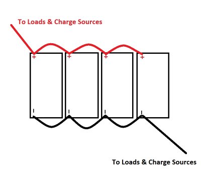
In the latter cross connected configuration I find the batteries in the bank are far more in-balance than in the first drawing. All I can compare to are the end connected and cross connected diagrams/methods in this post.
Perhaps someone out there has wired their boat to Smart Gauge #3 but I've never seen one or seen a huge need, based on conductance and pulsed load tests I've done. I have no doubt that it may be better but I don't know if it would be the same type of measurable improvement as going from end to cross connected.
Many banks that are cross connected have all the batteries within a margin of error for the analyzers. Battery banks end connected rarely do, especially beyond year one. I do see measurable reason to wire per the second diagram in this post but can't effectively comment on Smart Gauge Method #3 because I have never seen any boat wired like that .....
|
|
|
|
|
02-06-2012, 05:08
|
#18
|
|
Registered User
Join Date: Feb 2010
Posts: 250
|
Re: Battery Cabling for Parallel Bank
Quote:
Originally Posted by Maine Sail
I've never come across boat wired to the Smart Gauge method #3 (I think) with each battery having an equal length lead to a single post.
I have however seen many banks end connected like this:
And cross connected like this:
In the latter cross connected configuration I find the batteries in the bank are far more in-balance than in the first drawing. All I can compare to are the top and bottom diagrams/methods in this post.
Perhaps someone has wired their boat to Smart Gauge #3 but I've never seen one or seen a huge need, based on conductance and pulsed load tests I've done. Many banks cross connected have all the batts within a margin of error for the meters. Battery banks end connected rarely do especially beyond year one. I do see good reason to wire per the second diagram in this post but can't effectively comment on the Smart Gauge version using a single post for pos & neg.... |
Thanks for the reply. I wired mine exactly like your second drawing, so hopefully I'll get good milage out of them.
|
|
|
|
|
02-06-2012, 09:52
|
#19
|
|
Sponsoring Vendor

Join Date: Dec 2003
Location: South Carolina
Boat: Philip Rhodes Custom
Posts: 414
|
Re: Battery Cabling for Parallel Bank
If your battery to battery jumpers are of adequate size (at least as heavy as your starter motor cables) then as I pointed out the voltage difference between battery 1 and battery n is going to be millivilts. If you have that little difference in voltage then the current drawn from that battery will have little difference from battery to battery.
The jumper resistance is small compared to each battery's internal resistance and it is internal resistance that governs how much current each can supply. Even with identical batteries that internal resistance will vary much more than the overall resistance of different battery connection systems.
Despite the "evidence" of hundreds of examples of the first battery dying first who made this analysis? This is a personal opinion and not a statistic. There are so many factors that relate to battery life the minor difference in discharge load will be immaterial in comparison. Working on dozens of boats over the years I've not noticed any definable relationship between battery wiring layout and failure.
If the batteries were originally matched and one has reached (natural) end of life then you can bet that they all are dying. Under those conditoins just replacing the dead or weakest one will put most of the load on the new battery while you squeeze the last few % of life out of the remainder.
Suggestions that charging would be unequal are totally wrong. As batteries approach full charge, the current approaches zero. As the current approcahes zero, any voltage drop in the battery connections also approaches zero so they will eventually all be at the same charged voltage.
|
|
|
|
|
02-06-2012, 10:18
|
#20
|
|
Moderator

Join Date: Jul 2007
Boat: Bestevaer.
Posts: 14,678
|
Re: Battery Cabling for Parallel Bank
Quote:
Originally Posted by Andina
If your battery to battery jumpers are of adequate size (at least as heavy as your starter motor cables) then as I pointed out the voltage difference between battery 1 and battery n is going to be millivilts. If you have that little difference in voltage then the current drawn from that battery will have little difference from battery to battery.
The jumper resistance is small compared to each battery's internal resistance and it is internal resistance that governs how much current each can supply. Even with identical batteries that internal resistance will vary much more than the overall resistance of different battery connection systems.
Despite the "evidence" of hundreds of examples of the first battery dying first who made this analysis? This is a personal opinion and not a statistic. There are so many factors that relate to battery life the minor difference in discharge load will be immaterial in comparison. Working on dozens of boats over the years I've not noticed any definable relationship between battery wiring layout and failure.
If the batteries were originally matched and one has reached (natural) end of life then you can bet that they all are dying. Under those conditoins just replacing the dead or weakest one will put most of the load on the new battery while you squeeze the last few % of life out of the remainder.
Suggestions that charging would be unequal are totally wrong. As batteries approach full charge, the current approaches zero. As the current approcahes zero, any voltage drop in the battery connections also approaches zero so they will eventually all be at the same charged voltage. |
The main problem seen when charging is the difference in bulk charge voltage between the batteries if wired incorrectly. It is more of a problem on boats that charge primarily from a generator or high powered alternators. The voltage diffence for boats charging primarily from solar is small.
Bulk charging voltages are important and boats often push the limit of what is acceptable to recharge the batteries as quickly as possible. A small voltage drop in the interconnect cables will alter the bulk charging voltage that each battery receives significantly. Even if the final soc equalises between the batteries in time, the first battery ( if wired incorrectly ) will have been subject to higher bulk charge voltage, particularly initially.
|
|
|
|
|
02-06-2012, 13:34
|
#21
|
|
Sponsoring Vendor
Join Date: Dec 2003
Location: South Carolina
Boat: Philip Rhodes Custom
Posts: 414
|
Re: Battery Cabling for Parallel Bank
Sorry I have to disagree.
(Please no one take this personally, I enjoy a debate on these subjects, I feel a responsibility to correct misconceptions based on hearsay and non-scientific facts. Despite being a girl I've been a qualified electrical engineer since before most of you were born  . I've worked in telephone exchanges with lead acid batteries that can melt a 3"x 2" bus bar and distort it enough to tear it off the mountings from the magnetic forces of a short circuit. I've done marine electrical work for 20+ years. ).
If you are mixing battery types you do have to select a bulk charge mode (assuming you have a choice) for the most sensitive battery in the mix. This will extend charging time over what may have been achieved had they all had the same "higher" bulk setting.
BUT when charging on the hook, you virtually never charge much over 90% due to inefficient use of fuel once the bulk settings kick in and for most of that 90% they will be charging at maximum charger output so the tweaking for maximum voltage depending on chemistry has not yet kicked in.
Batteries charge with CURRENT not VOLTAGE. True the higher the voltage the higher the current will be but we are talking about a full battery voltage of about 12.8 and forcing current in by using charger source voltages of 14.2 to 15.6 depending on level of charge and chemistry setting. The resistance of the charging source, the cables, and the internal battery resistance governs the current going into the battery. So, for example charger output of 14.8 minus battery charge state equivalent to 12.6 gives a difference of 2.2 volts driving the current. A few millivolts difference in 2.2 volts due to inches of battery cable length is not going to make any measurable difference to the amp-hours going into the battery and total charge stored is maximum output current of the charging source. The difference due to bulk charge voltage limits being reached due to a few millivolts is non-existent.
Just do the simple math:-
Gauge 0 wire has a resistance of 0.0001 ohms per foot.
Even if the INEQUALITY of battery leads was TEN FEET, and you have a charging source putting out 50 amps, the voltage difference is 50x10x0.0001 = 0.005 volts. Forget it, you are making mountains out of mole hills.,
|
|
|
|
|
02-06-2012, 15:11
|
#22
|
|
Moderator
Join Date: Jul 2007
Boat: Bestevaer.
Posts: 14,678
|
Re: Battery Cabling for Parallel Bank
Quote:
Originally Posted by Andina
Sorry I have to disagree.
(Please no one take this personally, I enjoy a debate on these subjects, I feel a responsibility to correct misconceptions based on hearsay and non-scientific facts. Despite being a girl I've been a qualified electrical engineer since before most of you were born . I've worked in telephone exchanges with lead acid batteries that can melt a 3"x 2" bus bar and distort it enough to tear it off the mountings from the magnetic forces of a short circuit. I've done marine electrical work for 20+ years. ).
If you are mixing battery types you do have to select a bulk charge mode (assuming you have a choice) for the most sensitive battery in the mix. This will extend charging time over what may have been achieved had they all had the same "higher" bulk setting.
BUT when charging on the hook, you virtually never charge much over 90% due to inefficient use of fuel once the bulk settings kick in and for most of that 90% they will be charging at maximum charger output so the tweaking for maximum voltage depending on chemistry has not yet kicked in.
Batteries charge with CURRENT not VOLTAGE. True the higher the voltage the higher the current will be but we are talking about a full battery voltage of about 12.8 and forcing current in by using charger source voltages of 14.2 to 15.6 depending on level of charge and chemistry setting. The resistance of the charging source, the cables, and the internal battery resistance governs the current going into the battery. So, for example charger output of 14.8 minus battery charge state equivalent to 12.6 gives a difference of 2.2 volts driving the current. A few millivolts difference in 2.2 volts due to inches of battery cable length is not going to make any measurable difference to the amp-hours going into the battery and total charge stored is maximum output current of the charging source. The difference due to bulk charge voltage limits being reached due to a few millivolts is non-existent.
Just do the simple math:-
Gauge 0 wire has a resistance of 0.0001 ohms per foot.
Even if the INEQUALITY of battery leads was TEN FEET, and you have a charging source putting out 50 amps, the voltage difference is 50x10x0.0001 = 0.005 volts. Forget it, you are making mountains out of mole hills., |
No problems Andina I have never understood why people take these technical discussions personally.
The gauge 0 (50mm square) wire you quote is bigger than most people use, but the big problem with your calculations is that you are making no allowance for the resistance of each of the connections crimps, battery terminals etc.
The resistance of these connections varies signifficantly in practice and is therefore difficult to estimate.
If we use the estimate in the Smart gauge web page of 1.5x10⁻³ ohms per link for 10 links and a 50A current it gives 0.75v ! From the resistance in the connections only.
6 batteries is more connections than most people will have and I think they have overestimated the resistance of these connections.
In practice voltage drops are easy to measure and values of about 0.2v are what is usually seen. This is a significant difference in bulk charging voltage.
|
|
|
|
|
02-06-2012, 15:28
|
#23
|
|
Moderator
Join Date: Aug 2009
Location: Solent, England
Boat: Moody 31
Posts: 18,458
|
Re: Battery Cabling for Parallel Bank
Quote:
Originally Posted by Maine Sail
I've never come across any boat wired to the Smart Gauge Method #3 version (Image Courtesy Smart Gauge)
Smart Gauge Method #3
.. |
We might be going with this method, because I can't think of how otherwise to wire up 3 x 12v house batteries equally. The current two batteries are easy and in perfect harmony.
Pete
|
|
|
|
|
02-06-2012, 16:36
|
#24
|
|
Sponsoring Vendor
Join Date: Dec 2003
Location: South Carolina
Boat: Philip Rhodes Custom
Posts: 414
|
Re: Battery Cabling for Parallel Bank
Worst case even 0.2 volts is not significant during the bulk charging stage.
During bulk charging the source is a CONSTANT CURRENT supply so if there is an extra 0.2 volts in the series connection, the source will go up 0.2 volts to maintain constant (maximum) current. It is not until that extra increase reached the bulk mode voltage threshold that it might switch to the next stage slightly sooner but by then the batteries already have 85% of their charge.
|
|
|
|
|
02-06-2012, 17:00
|
#25
|
|
Registered User
Join Date: Jun 2011
Location: Tasmania, Australia
Boat: Bieroc 36 foot Ketch
Posts: 4,953
|
Re: Battery Cabling for Parallel Bank
Thank you Maine Sail, wonderful articles. I've also printed out your 1 Both 2 OFF article which is great and I'm going to use. Looks like I need to get myself an echo charger or an ACR.. would you have a preference?
|
|
|
|
|
02-06-2012, 17:03
|
#26
|
|
Registered User
Join Date: Feb 2010
Posts: 250
|
Re: Battery Cabling for Parallel Bank
Quote:
Originally Posted by Andina
Sorry I have to disagree.
(Please no one take this personally, I enjoy a debate on these subjects, I feel a responsibility to correct misconceptions based on hearsay and non-scientific facts. Despite being a girl I've been a qualified electrical engineer since before most of you were born . I've worked in telephone exchanges with lead acid batteries that can melt a 3"x 2" bus bar and distort it enough to tear it off the mountings from the magnetic forces of a short circuit. I've done marine electrical work for 20+ years. ).
If you are mixing battery types you do have to select a bulk charge mode (assuming you have a choice) for the most sensitive battery in the mix. This will extend charging time over what may have been achieved had they all had the same "higher" bulk setting.
BUT when charging on the hook, you virtually never charge much over 90% due to inefficient use of fuel once the bulk settings kick in and for most of that 90% they will be charging at maximum charger output so the tweaking for maximum voltage depending on chemistry has not yet kicked in.
Batteries charge with CURRENT not VOLTAGE. True the higher the voltage the higher the current will be but we are talking about a full battery voltage of about 12.8 and forcing current in by using charger source voltages of 14.2 to 15.6 depending on level of charge and chemistry setting. The resistance of the charging source, the cables, and the internal battery resistance governs the current going into the battery. So, for example charger output of 14.8 minus battery charge state equivalent to 12.6 gives a difference of 2.2 volts driving the current. A few millivolts difference in 2.2 volts due to inches of battery cable length is not going to make any measurable difference to the amp-hours going into the battery and total charge stored is maximum output current of the charging source. The difference due to bulk charge voltage limits being reached due to a few millivolts is non-existent.
Just do the simple math:-
Gauge 0 wire has a resistance of 0.0001 ohms per foot.
Even if the INEQUALITY of battery leads was TEN FEET, and you have a charging source putting out 50 amps, the voltage difference is 50x10x0.0001 = 0.005 volts. Forget it, you are making mountains out of mole hills., |
Andina, So what is your bottom line to the electrically challenged (like myself) for wiring batteries? It sounds like you feel it doesn't really matter how they are wired, provided one uses large enough cable. Correct? Is gauge 0 what you would typically recommend for wire size?
|
|
|
|
|
02-06-2012, 23:39
|
#27
|
|
Moderator
Join Date: Jul 2007
Boat: Bestevaer.
Posts: 14,678
|
Re: Battery Cabling for Parallel Bank
Quote:
Originally Posted by Andina
Worst case even 0.2 volts is not significant during the bulk charging stage.
During bulk charging the source is a CONSTANT CURRENT supply so if there is an extra 0.2 volts in the series connection, the source will go up 0.2 volts to maintain constant (maximum) current. It is not until that extra increase reached the bulk mode voltage threshold that it might switch to the next stage slightly sooner but by then the batteries already have 85% of their charge.
|
0.2 v is a significant difference in the bulk charging voltage. It cannot be compensated for, because it is a difference between the batteries ( this is if they are not wired correctly). So we have a choice of one battery receiving a bulk voltage charge that it 0.2v too high, or one battery that is receiving a bulk voltage that is 0.2v too low. In the former case the high voltage causes some damage in the later case the the soc is lower so the battery is discharged further. The only way we can try and compensate is to pick the lower voltage and run the generator/main engine longer and no one wants to do that when the problem is fixed with a simple change to the wiring.
Boat charging sources (alternator regulators, solar controlers etc) are not constant current. They maintain fixed voltage points. In the better products the voltage can be adjusted so it optimum at the batteries, but if the battery voltage is different between batteries, because of incorrect wiring, a compromise must be chosen. Wiring the batteries correctly is easy and means that no compromise is needed ( connecting the positive and negative to the different ends is fine IMHO and I don't think for most installations the star system is worthwhile)
I don't mean to imply that you batteries will die a very quick death if wired incorrectly, but getting these details right together with other important issues like charging voltages will make make a significant difference to life you get out of those expensive batteries. Battery wiring is easy and cheap to do right.
|
|
|
|
|
03-06-2012, 08:25
|
#28
|
|
Registered User
Join Date: Jan 2011
Posts: 243
|
Quote:
|
Originally Posted by slowshoes
Andina, So what is your bottom line to the electrically challenged (like myself) for wiring batteries? It sounds like you feel it doesn't really matter how they are wired, provided one uses large enough cable. Correct? Is gauge 0 what you would typically recommend for wire size?
|
Are you asking about the jumpers or the mains to the switch and distribution? The latter depends on your load, the length of your circuit, and how much voltage drop your more finicky devices can tolerate. There are tables showing the ampacity and voltage drop for different conductor sizes depending on ambient temperatures, voltage, and load. I think Blue Sea Systems and other manufacturers have charts on their website.
I'm curious to know what Andina says about the jumpers. I use the same gauge as I use for the mains.
|
|
|
|
|
03-06-2012, 08:43
|
#29
|
|
Sponsoring Vendor
Join Date: Dec 2003
Location: South Carolina
Boat: Philip Rhodes Custom
Posts: 414
|
Re: Battery Cabling for Parallel Bank
Quote:
Originally Posted by slowshoes
Andina, So what is your bottom line to the electrically challenged (like myself) for wiring batteries? It sounds like you feel it doesn't really matter how they are wired, provided one uses large enough cable. Correct? Is gauge 0 what you would typically recommend for wire size?
|
Good mechanical work is more important than the electrical contortions.
Use a wire gauge at least as heavy as your starter cables, heavier is better.
Lay out the wiring for the most convenient mechanical arrangement, shortest runs, minimum total cable. It helps ifyou can to minimize the number of cables on each battery terminal. Clean solid battery connections will minimize resistance much more than agonizing over the wire resistance in the electrical layout.
|
|
|
|
|
03-06-2012, 08:59
|
#30
|
|
Sponsoring Vendor
Join Date: Dec 2003
Location: South Carolina
Boat: Philip Rhodes Custom
Posts: 414
|
Re: Battery Cabling for Parallel Bank
Quote:
Originally Posted by noelex 77
0.2 v is a significant difference in the bulk charging voltage. It cannot be compensated for, because it is a difference between the batteries ( this is if they are not wired correctly). So we have a choice of one battery receiving a bulk voltage charge that it 0.2v too high, or one battery that is receiving a bulk voltage that is 0.2v too low. In the former case the high voltage causes some damage in the later case the the soc is lower so the battery is discharged further. The only way we can try and compensate is to pick the lower voltage and run the generator/main engine longer and no one wants to do that when the problem is fixed with a simple change to the wiring.
Boat charging sources (alternator regulators, solar controlers etc) are not constant current. They maintain fixed voltage points. In the better products the voltage can be adjusted so it optimum at the batteries, but if the battery voltage is different between batteries, because of incorrect wiring, a compromise must be chosen. Wiring the batteries correctly is easy and means that no compromise is needed ( connecting the positive and negative to the different ends is fine IMHO and I don't think for most installations the star system is worthwhile)
I don't mean to imply that you batteries will die a very quick death if wired incorrectly, but getting these details right together with other important issues like charging voltages will make make a significant difference to life you get out of those expensive batteries. Battery wiring is easy and cheap to do right. |
No, if one battery is 0.2 volts less than another during the bulk charging mode the difference in charging current entering the battery will be negligible compared to other factors like internal battery resistance.
By the time the charger reaches the threshold of the bulk stage, the curren will no longer be 50 amps. At that stage the battery voltage has increased and the current has dropped to about 5 amps. So the 0.2 volts difference is now 0.02 volts. Differences in battery to battery characteristics will have more influence than 20 thousandts of a volt. Get real .
As the charging current approaches zero at full charge, the voltage drop across resistance also drops to zero so at full charge all batteries will be at the same voltage.
You are incorrect. All battery charging sources are (quasi) CONStANT CURRENT, not constant voltage as you claim. If they were constant voltage output the battery would have to be at the same voltage. But in fact the voltage out of the charging source INCREASES as the battery voltage INCREASES. They start out at (say) 12.4 volts and charge to (say) 14.2. You will see that voltage both on the battery terminals and on the charger terminals (they are connected together). That is hardly constant voltage.
|
|
|
|
|
|
| Thread Tools |
Search this Thread |
|
|
|
| Display Modes |
Rate This Thread |
 Linear Mode Linear Mode
|
|
 Posting Rules
|
You may not post new threads
You may not post replies
You may not post attachments
You may not edit your posts
HTML code is Off
|
|
|
|
Advertise Here

 Recent Discussions Recent Discussions |
|
|
|
|
|
|
|
|
|
|
|
|
|
|
|
|
|
|
|
|
|
|
|
|
|
Vendor Spotlight |
|
|
|
|
|
|
|
|
|


